Rockwell Automation 2100-GK61 DeviceNet to SCANport User Manual
Page 35
Publication 2100-UM001B-EN-P – January 2001
Configuring the DeviceNet to SCANport Communication Module with Digital Inputs
3-5
Important: If the module does not appear:
–
Verify there is an EDS file for the device. Refer to “Creating
an EDS file for your SCANport Product” in Chapter 4,
Configuring a Scanner to Communicate with the
Adapter.
–
Verify that the device has a unique node address. Check the
network LED on the module. If it is red, it is not an unique
address. You must configure the module in a point-to-point
connection.
6. Double-click the icon for the 2100-GK61 module. (In our
example, it is node 63 in Figure 3.3.)
The DeviceNet Configuration screen appears for the selected device.
The screen has three tabs to choose from: General, Device
Parameters, and EDS I/O Default.
The General tab allows you to give the device a name and add a
description for the device. These names and descriptions will be used
to represent and describe the product throughout RSNetWorx for
DeviceNet.
The DeviceNet Parameters and EDS I/O Default tabs allow you to
see the parameters and configuration of the device selected.
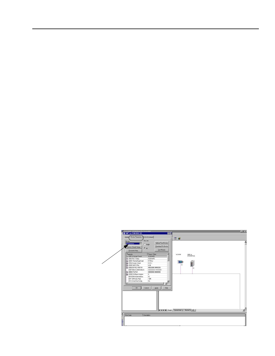
7. Click on the Device Parameters tab. A dialog box requesting to
upload or download the device’s parameters appears. Click on the
Upload button to upload the parameters from the module. The
screen listing all the device’s parameters appears. In this example
the 2100-GK61 is configured with an SMP3 device.
Figure 3.4
Device Parameters, all
Step #7