Rockwell Automation 2100-GK61 DeviceNet to SCANport User Manual
Page 188
Publication 2100-DU021B-EN-P - January 2004
Ladder Logic Programming—Including Reading Inputs 5-3
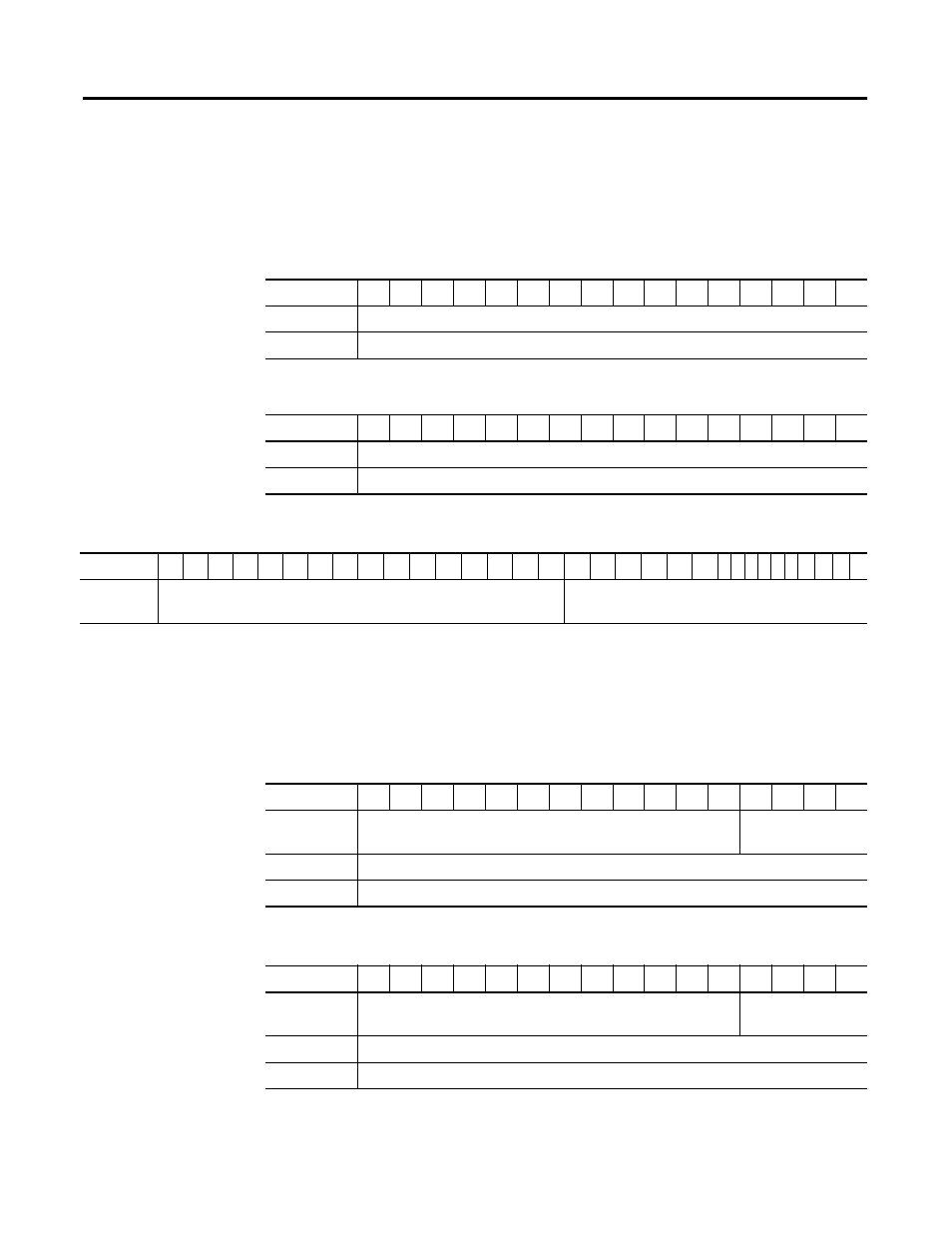
2100-GK61 Scanner Output: See Chapter 4 for configuring a scanner. The 1st
word consists of command bits for the SCANport product (such as Drive,
SMC or SMP-3). The 2nd word is an analog reference supported for Drives,
but not for an SMC or SMP-3.
Table 5.A Scanner Output Map (PLC Example)
Table 5.B Scanner Output Map (SLC Example)
Table 5.C Scanner Output Map (ControlLogix Example)
2100-GK61 Scanner Input: See Chapter 4 for configuring a scanner. The
scanner’s first (4) bits of 1st word are 2100-GK61 discrete inputs. Bit 4
through 15 of 1st word are not used. The 2nd word is status of SCANport
product (such as a Drive or SMC) and the 3rd word is the analog feedback.
Table 5.D Scanner Input Map (PLC Example)
Table 5.E Scanner Input Map (SLC Example)
Bits 15 - 0
15
14
13
12
11
10
9
8
7
6
5
4
3
2
1
0
N10:1
SCANport Device Command
N10:2
Analog Reference (For Drives)
Bits 15 - 0
15
14
13
12
11
10
9
8
7
6
5
4
3
2
1
0
O:1.1
Command or Logic Control Data for a Drive, SMC or SMP-3
O:1.2
Analog Reference (For Drives)
Bits 15 - 0
31 30 29 28 27 26 25 24 23
22
21
20
19
18
17
16
15
14
13 12
11
10
9 8 7 6 5 4 3 2 1 0
1:I.Data[0]
Analog Reference (For Drives)
Command or Logic Control Data for a Drive, SMC or
SMP-3
Bits 15 - 0
15
14
13
12
11
10
9
8
7
6
5
4
3
2
1
0
N9:1
Not Used
2100-GK61 Discrete
Inputs
N9:2
Status Data for a Drive, SMC or SMP-3
N9:3
Analog Feedback for a Drive, SMC or SMP-3
Bits 15 - 0
15
14
13
12
11
10
9
8
7
6
5
4
3
2
1
0
I:1.1
Not Used
2100-GK61 Discrete
Inputs
I:1.2
Status Data for a Drive, SMC or SMP-3
I:1.3
Analog Feedback for a Drive, SMC or SMP-3