Drive status structure, Logic control structure – Rockwell Automation 2100-GK61 DeviceNet to SCANport User Manual
Page 190
Publication 2100-DU021B-EN-P - January 2004
Ladder Logic Programming—Including Reading Inputs 5-5
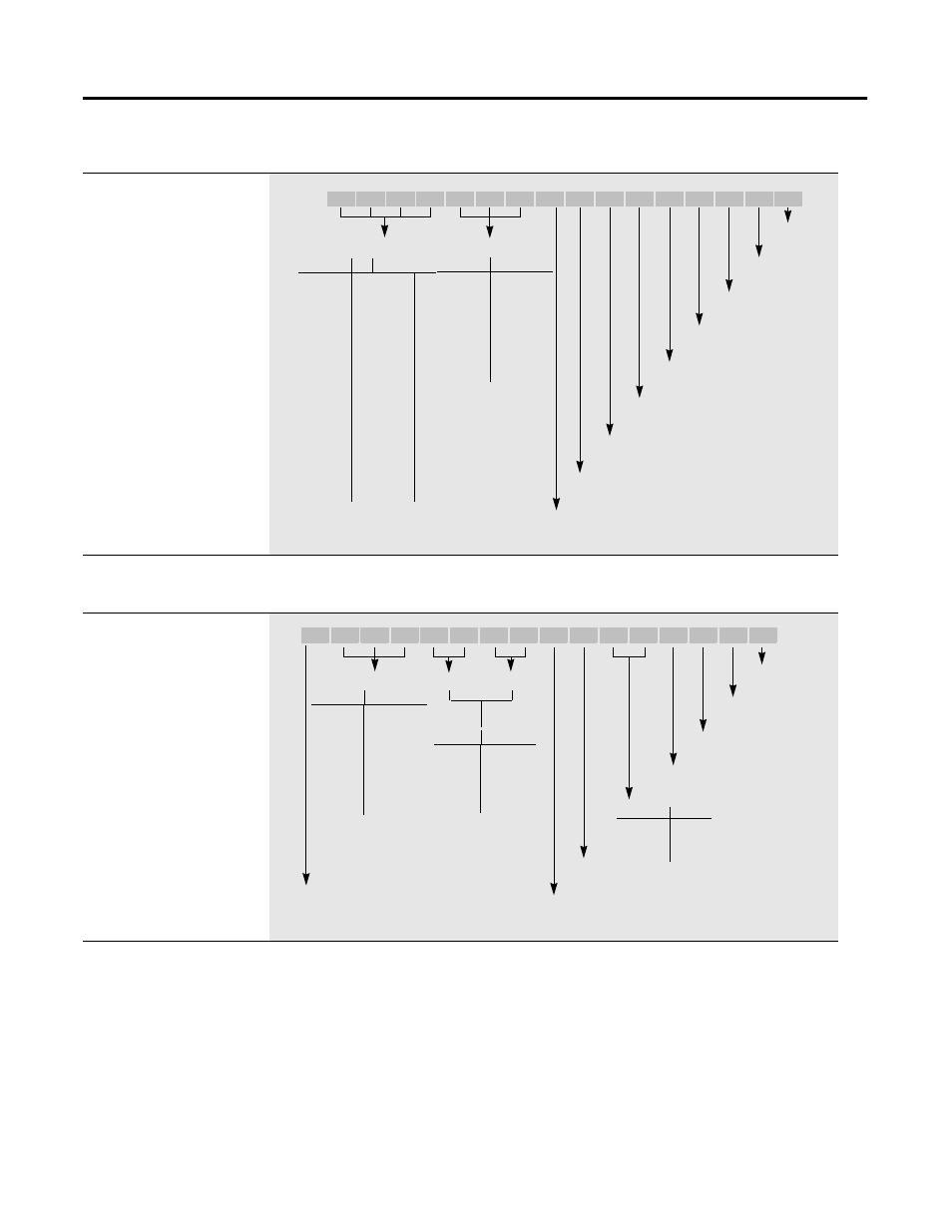
Figure 5.2 The 1305, 1336 PLUS or 1336 PLUS II Drive in this example sends the
following logic status to the PLC via the scanner.
Figure 5.3 The 1305, 1336 PLUS or 1336 PLUS II Drive in this example accepts the
following logic command data from the PLC via the scanner.
Drive Status
Structure
This provides the drive status
information that will be sent to
the logic controller
’
s input im-
age table when the
Communication Module is set
to control the drive.
Reference
15
14
13
12
Freq Select 1
0
0
0
0
Preset Freq 1
0
0
0
1
Preset Freq 2
0
0
1
0
Preset Freq 3
0
0
1
1
Preset Freq 4
0
1
0
0
Preset Freq 5
0
1
1
0
Preset Freq 6
0
1
1
0
Preset Freq 7
0
1
1
1
Freq Select 2 1
0
0
0
Adapter 1
1
0
0
1
Adapter 2
1
0
1
0
Adapter 3
1
0
1
1
Adapter 4
1
1
0
0
Adapter 5
1
1
0
1
Adapter 6
1
1
1
0
Jog Frequency
1
1
1
1
Bit 15
Bit 13Bit 12Bit 11Bit 10 Bit 9 Bit 8 Bit 7 Bit 6 Bit 5 Bit 4 Bit 3 Bit 2 Bit 1 Bit 0
Bit 14
Running
1 = Running
0 = Not Running
Enabled
1 = Enabled
0 = Not Enabled
Command Direction
1 = Forward
0 = Reverse
Accelerating
1 = Accelerating
0 = Not Accelerating
Rotating Direction
1 = Forward
0 = Reverse
Decelerating
1 = Decelerating
0 = Not Decelerating
Alarm
1 = Alarm
0 = No Alarm
At Speed
1 = At Speed
0 = Not at Speed
Fault
1 = Faulted
0 = Not Faulted
Reference ID
Local Adapter ID
Local
11
10
9
TB3
0
0
0
1
0
0
1
2
0
1
0
3
0
1
1
4
1
0
0
5
1
0
1
6
1
1
0
Unused
1
1
1
Logic Control
Structure
This information provides the
control logic information that is
sent to the drive through the
logic controller
’
s output image
table when the Communication
Module is set to control the
drive.
Bit 15
Bit 13Bit 12Bit 11Bit 10 Bit 9 Bit 8 Bit 7 Bit 6 Bit 5 Bit 4 Bit 3 Bit 2 Bit 1 Bit 0
Bit 14
Start
1 = Start
0 = Not Start
Stop
1 = Stop
0 = Not Stop
Jog
1 = Jog
0 = Not Jog
Clear Faults
1 = Clear Faults
0 = Not Clear Faults
Local
1 = Local Lockout
0 = Not Local
MOP Increment
1 = Increment
0 = Not Increment
MOP Decrement
1 = Decrement
0 = Not Decrement
Reference Select
Decel Time
Accel Time
Time
9/11
8/10
No
Command
0
0
Time 1
0
1
Time 2
1
0
Hold Time
1
1
Reference
14
13
12
No Command
0
0
0
Freq Select 10
0
0
1
Freq Select 20
0
1
0
Preset Freq 30
0
1
1
Preset Freq 40
1
0
0
Preset Freq 50
1
0
1
Preset Freq 60
1
1
0
Preset Freq 70
1
1
1
Direction
5
4
No Command
0
0
Forward
0
1
Reverse
1
0
Hold Direction
1
1