Rockwell Automation 2100-GK61 DeviceNet to SCANport User Manual
Page 53
Publication 2100-UM001B-EN-P – January 2001
Configuring a Scanner to Communicate with the Adapter
4-17
The dialog box contains 6 data tabs which are used to configure
various portions of the scanner. The General tab allows the user to
edit the name and descriptions of the scanner. The Module tab allows
the user to configure the scanner setup properties. The Scanlist tab
allows the user to choose which components the scanner will scan for
data. The Input and Output tab is where the user sets up where the
data from the scanned devices is kept to be used by the PLC
processor. Finally, the Summary tab allows the user to view a concise
summary of how the scanner has been configured.
2. On the General page, place the cursor in the name field and type
the name you want to assign the scanner. If you want to add a
description to the scanner, place the cursor in the description field
and enter a description. Click on the Apply button to save the
information.
3. Click on the Module tab. A dialog box will appear requesting to
upload or download information from the scanner. Click on
Upload. All the scanlist information currently stored in the
scanner will be uploaded. Once the upload is complete, the
Module screen will appear.
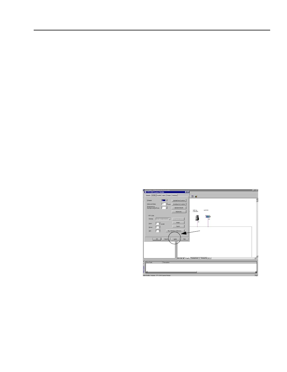
Figure 4.23
1771 SDN Module Screen
Verify the default values listed on this page. Edit them as necessary.
Refer to RSNetworx for DeviceNet online help for more information.
4. Click Apply to save.
Step #4