Allied Telesis AlliedView-EMS 3.11 DEVICE MANAGEMENT User Manual
Page 321
AlliedView™-EMS 3.11 Device Management Guide
Page 321 of 402
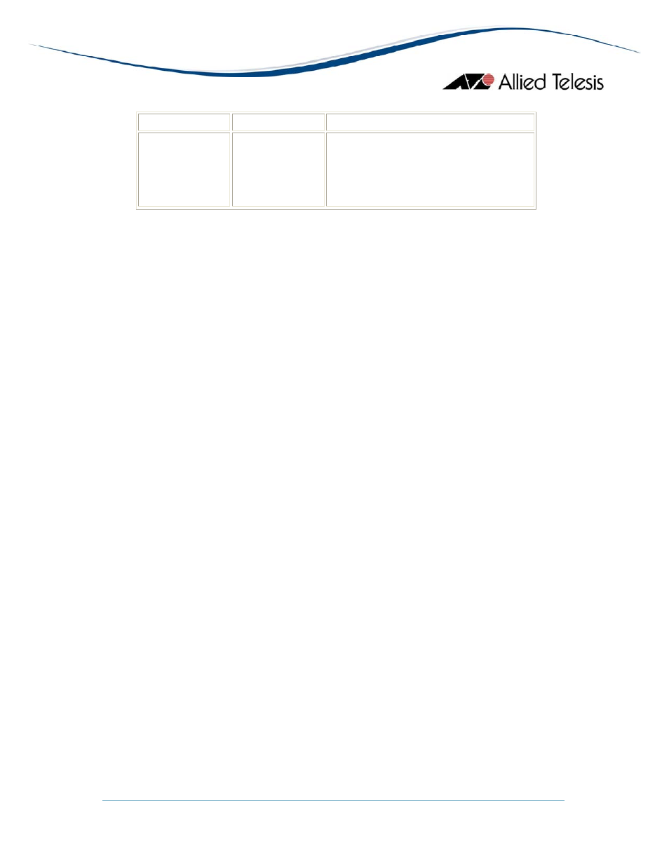
Left Bay
Right Bay
Numbering
AT-XEM-12S
AT-XEM-12T
AT-XEM-12S
AT-XEM-12T
1 to 49 (Ports 25 to 36 will show data
for ports on the left bay. Ports 37 to 48
will show data for ports on the right
bay. Port 49 is invalid and should be
ignored.)
Bandwidth Limits
Displays bandwidth limits of the switch ports.
Note
- The current firmware version does not allow the Ingress Limit parameter to
be configured.
Error Statistics
Displays error statistics.
Note
- The following parameters are not applicable to the AT-x900-24X series and
should be ignored:
• Ethernet Chip Set
• Symbol Errors
• Duplex Status
• Rate Control Ability
• Rate Control Status
Spanning Tree Info
Displays the port's spanning tree parameters.
Note
- The Path Cost Contribution parameter is not applicable to the AT-x900-24X
series and should be ignored.
Note
- Valid MIB Set values for the Port Path Cost parameter is in the range [1-
65535] inclusive.
MAU Info
Displays interface-related MAU information for the port.
Note
- The MAU Type List Bits and HC False Carriers parameters are not applicable
to the AT-x900-24X series and should be ignored.
Note
- The MAU Status and Default MAU Type parameters are implemented as
'read-only'.
MAU Negotiation Info
Displays the MAU's auto-negotiation settings and its status.