Wiring the series pd, Wiring, Power wiring – Watlow Series PD User Manual
Page 8
W a t l o w S e r i e s P D
■
6
■
C h a p t e r 2 I n s t a l l a n d W i r e
Ó
Warning:
Use National Electric (NEC) or
other country-specific standard
wiring and safety practices when
wiring and connecting this con-
troller to a power source and to
electrical sensors or peripheral
devices. Failure to do so may re-
sult in damage to equipment and
property, and/or injury or loss of
life.
Ó
WARNING: If high voltage is ap-
plied to the controller, irre-
versible damage will occur.
Note: 24 VЕ
Е input power re-
quired to use single cycle,vari-
able time base output function.
Wiring the Series PD
The model number for each output option appears with its wiring diagram.
Check the label on the controller and compare your model number to those
shown here and to the model number breakdown in the Appendix of this
manual.
All outputs are referenced to a de-energized state.
All wiring and fusing must conform to the National Electric Code and to
any locally applicable codes as well.
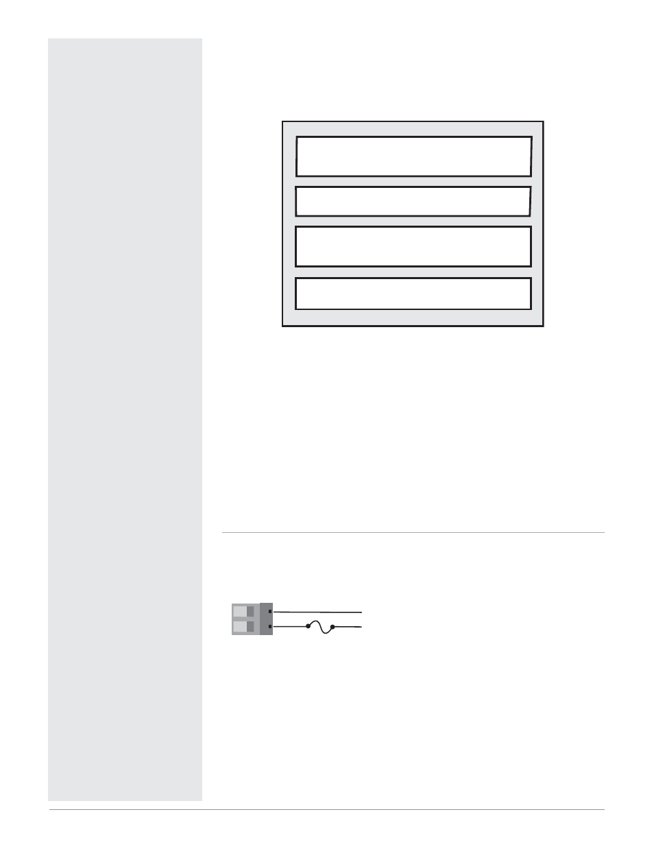
Figure 6a —
Power Wiring
(all model numbers)
• Nominal voltage: 24V‡ (ac/dc)
25 26
25
26
-
+
24V‡ (ac/dc)
L2
L1
Isolation Blocks
There are no electrical connections between these blocks
Relay outputs (mechanical and solid-state) provide isolation through their
relay contacts. Each relay output is isolated from the blocks above and is
isolated from other relay outputs.
Analog Input 1
Digital Inputs
Current Transformer Inputs
Analog Input 2
Control Outputs
Alarm Outputs
Retransmit Outputs
Communications