Input 1, 0 to 10v о о (dc) process input, Input 2, 0 to 10v о о (dc) process input – Watlow Series PD User Manual
Page 10
W a t l o w S e r i e s P D
■
8
■
C h a p t e r 2 I n s t a l l a n d W i r e
ç
Warning:
Use National Electric (NEC) or
other country-specific standard
wiring and safety practices when
wiring and connecting this con-
troller to a power source and to
electrical sensors or peripheral
devices. Failure to do so may re-
sult in damage to equipment and
property, and/or injury or loss of
life.
ç
WARNING: Process input may
not have sensor break protec-
tion. Outputs can remain full on.
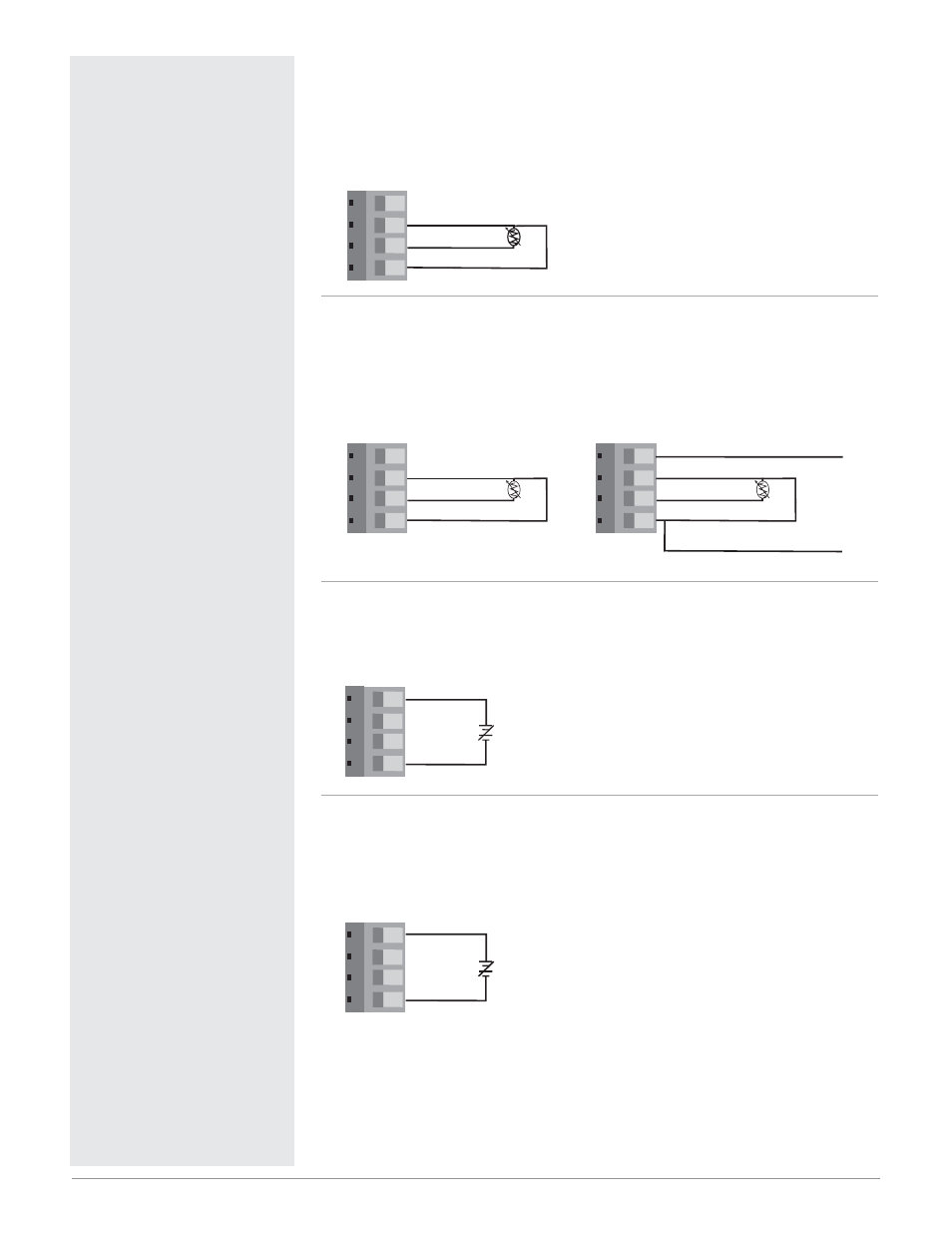
Figure 8a —
2-Wire RTD Input 2 (100
Ω
DIN curve 0.00385
Ω
/
Ω
/°C)
PDD _-_ _ _ _-_ _ _ _
Terminals 5 and 7 must be shorted for a two-wire RTD.
• Nominal excitation current: 250
µ
A
Figure 8b —
3-Wire RTD Input 2 (100
Ω
DIN curve 0.00385
Ω
/
Ω
/°C)
PDD _-_ _ _ _-_ _ _ _
The S1 lead (usually white) must be connected to terminal 6.
• Nominal excitation current: 250
µ
A
Figure 8c —
Input 1, 0 to 10VО
О (dc) Process Input
(all model numbers)
• Input impedance 20 k
Ω
, dc only
Figure 8d —
Input 2, 0 to 10VО
О (dc) Process Input
PDD _-_ _ _ _-_ _ _
• Input impedance 20 k
Ω
, dc only
• Input 2 isolated from Input 1
5
6 7 8
8
5
+
-
9
10 11 12
12
9
+
-
5
6 7 8
6 S1
7 S2
5 S3
8 INFOSENSE™ DATA
INFOSENSE™ GND
5
6 7 8
6 S1
7 S2
5 S3
5
6 7 8
6 S1
7 S2
5