Chapter three, Indicator lights, Chapter 3 - indicator lights – Watlow Series PD User Manual
Page 21
W a t l o w S e r i e s P D
■
1 9
■
C h a p t e r 3 I n d i c a t o r L i g h t s
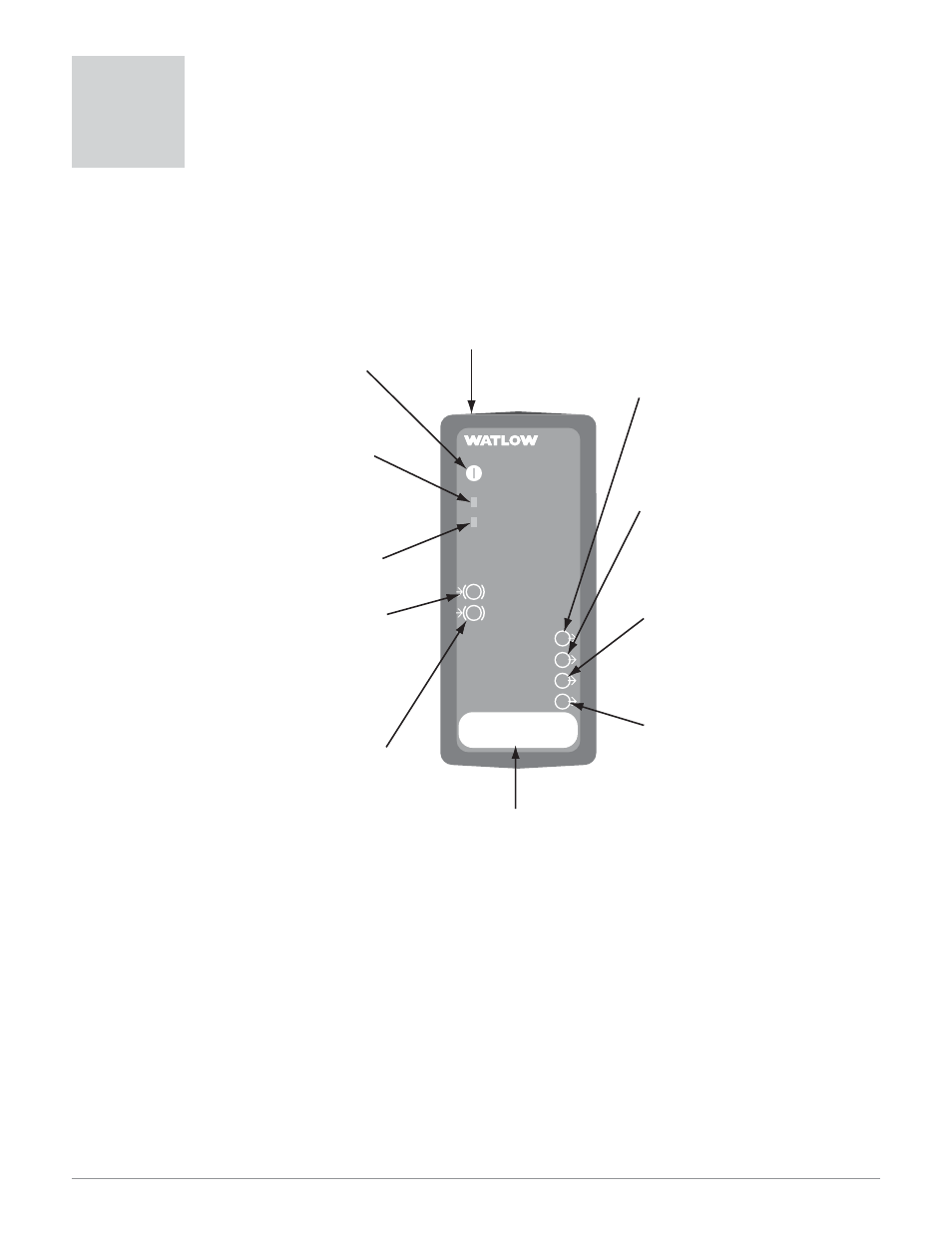
The Series PD controller may have up to nine LED indicator lights to help you monitor the
status of input power, Ethernet functions, input errors and outputs status. These LEDs can
provide a quick visual indication of basic controller functions. An additional heartbeat LED,
used for diagnostics, can be seen through the top vent at the back left side of the controller.
Heartbeat LED Diagnostics:
• Application Mode (normal operation) - 1 flash per second
• Test Mode (internal factory calibration) - 10 flashes per second
• Boot Code (internal factory configuration) - 1 flash per 2 seconds
Both Input Error LEDs Lit
• TFTP Mode (flash download in progress)
PD
PID Controller
Power
Ethernet Link
Ethernet Activity
1
2
3
4
1
2
Input Error
Input Error
Output
Output
Output
Output
Address
Power
Green light stays lit when the
power is on.
• If not lit or flashing, check
your power source.
Ethernet Link:
Green light is lit if the Ethernet
cable is correctly wired and
connected to a 10BaseT port.
• If not lit, check for the correct
RJ-45 cable and switch/hub speed.
Ethernet Activity
Green light is lit when commun-
ication activity occurs.
(1) Input Error
Red light is lit if there is a sensor
problem on Input 1. Lights momen-
tarily after power up.
• If it stays lit:
- Verify the sensor wiring, polarity
and function.
- Rewire or replace as necessary.
(2) Input Error
Red light is lit if there is a sensor
problem on Input 2. Lights momen-
tarily after power up.
• If it stays lit:
- Verify the sensor wiring, polarity
and function.
- Rewire or replace as necessary.
(1) Output
Red light is lit or flashes when
control Output 1 is active. If it does
not light up, the output is not active.
The output may be configured as an
event (alarm) or control.
(2) Output
Red light is lit or flashes when
control Output 2 is active. If it does
not light up, the output is not active.
The output may be configured as an
event (alarm) or control.
(3) Output
Red light is lit or flashes when
control Output 3 is active. If it does
not light up, the output is not active.
The output may be configured as an
event (alarm) or control.
(4) Output
Red light is lit or flashes when
control Output 4 is active. If it does
not light up, the output is not active.
The output may be configured as an
event (alarm) or control.
Address Field
Record the unit's Device Name
in erasable marker here. For example,
PD012345.
Heartbeat (diagnostics)
Green light can be seen on the left
side pc board, through the top vents
at the back of the unit.
Figure 18 — Series PD LED Indicator Lights
Indicator Lights
3