Chapter two, Install and wire, Chapter 2 - install and wire – Watlow Series PD User Manual
Page 5: Dimensions, Series pd dimensions
W a t l o w S e r i e s P D
■
3
■
C h a p t e r 2 I n s t a l l a n d W i r e
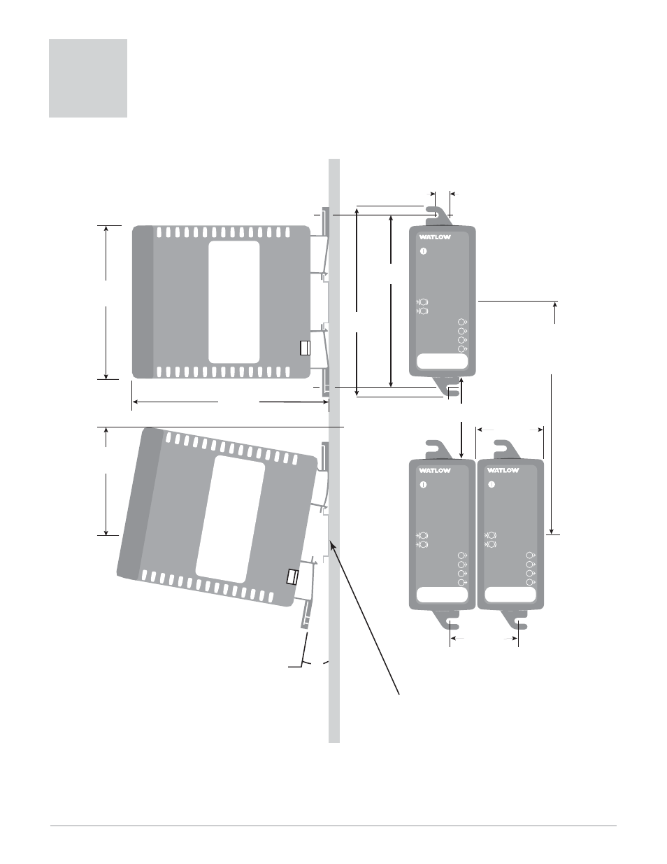
DIN
rail
bracket for
panel mounting
(M3.5 or #6
screw required)
Side View
Front View
8.1 mm
(0.32 in)
95.3 mm
(3.75 in)
72.9 mm
(2.87 in)
128.5 mm
(5.06 in)
Attachment Angle
10˚
DIN
rail
107.7 mm
(4.24 in)
118.4 mm
(4.66 in)
Min. Clearance 51 mm
(2 in)
Min. Clearance
between rail
centerlines
146.1 mm
(5.75 in)
41.7 mm
(1.64 in)
41.9 mm
(1.65 in)
Top/bottom
mount
hole offset
PD
PID Controller
Power
Ethernet Link
Ethernet Activity
1
2
3
4
1
2
Input Error
Input Error
Output
Output
Output
Output
Address
PD
PID Controller
Power
Ethernet Link
Ethernet Activity
1
2
3
4
1
2
Input Error
Input Error
Output
Output
Output
Output
Address
PD
PID Controller
Power
Ethernet Link
Ethernet Activity
1
2
3
4
1
2
Input Error
Input Error
Output
Output
Output
Output
Address
Use DIN EN 50022 35 X 7.5 mm rail
ç
Caution: Maintain the correct spacing be-
tween rows of controllers to allow suffi-
cient air circulation and installation clear-
ance. Failure to do so could result in
damage to equipment.
Figure 3 — Series PD dimensions
2
Install and Wire
Series PD Dimensions