Watlow Series PD User Manual
Page 164
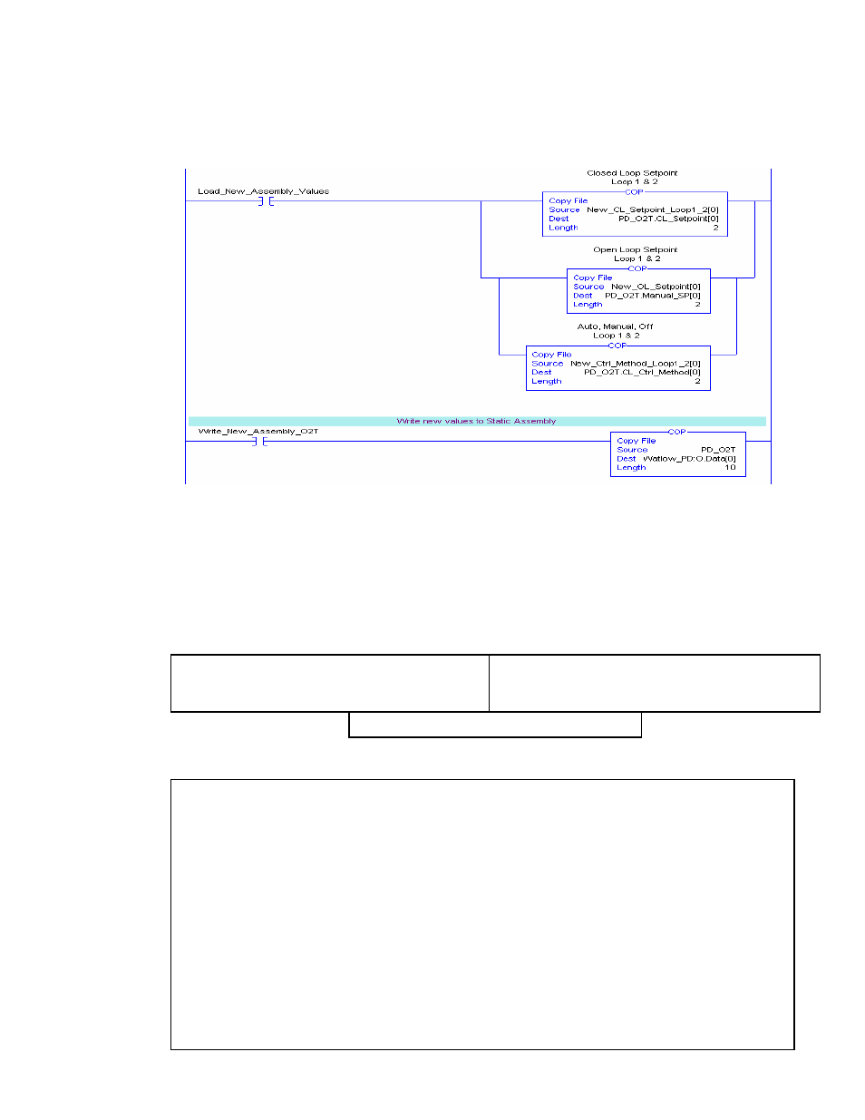
Below, the first rung of logic simply takes the new values entered into the tags
above and copies them to the appropriate tags in the array defined as PD_O2T.
As can be seen in figure 3.1.1a the source tags were formatted to correspond
with the format of the destination tags in the copy instructions.
Once the contact labeled “Load_New_Assembly_Values” is actuated the new
values will be loaded and ready to be transferred to the PD. The second rung,
when “Write_New_Assembly_O2T” is actuated will do a byte for byte transfer of
the source tags (ControlLogix) to the destination tags (PD).
In sections 2.2.1 and 2.2.2 above, words 17 and 18 of the input assembly are
defined as DIO_STATE and ALARM_STATUS respectively. The definition of the
bits within those words follows:
Figure 3.1.1b
Bit 00: 0 = Alarm #1 Inactive, 1 = Alarm #1 Active (tag_ALARM_STATUS Instance 1)
Bit 01: 0 = Alarm #2 Inactive, 1 = Alarm #2 Active (tag_ALARM_STATUS Instance 2)
Bit 02: 0 = Alarm #3 Inactive, 1 = Alarm #3 Active (tag_ALARM_STATUS Instance 3)
Bit 03: 0 = Alarm #4 Inactive, 1 = Alarm #4 Active (tag_ALARM_STATUS Instance 4)
Bit 04: 0 = Alarm #5 Inactive, 1 = Alarm #5 Active (tag_ALARM_STATUS Instance 5)
Bit 05: 0 = Alarm #6 Inactive, 1 = Alarm #6 Active (tag_ALARM_STATUS Instance 6)
Bit 06: 0 = Alarm #7 Inactive, 1 = Alarm #7 Active (tag_ALARM_STATUS Instance 7)
Bit 07: 0 = Alarm #8 Inactive, 1 = Alarm #8 Active (tag_ALARM_STATUS Instance 8)
Bit 08: 1 = Alarm #1 Silenced (tag_ALARM_STATUS Instance 1)
Bit 09: 1 = Alarm #2 Silenced (tag_ALARM_STATUS Instance 2)
Bit 10: 1 = Alarm #3 Silenced (tag_ALARM_STATUS Instance 3)
Bit 11: 1 = Alarm #4 Silenced (tag_ALARM_STATUS Instance 4)
Bit 12: 1 = Alarm #5 Silenced (tag_ALARM_STATUS Instance 5)
Bit 13: 1 = Alarm #6 Silenced (tag_ALARM_STATUS Instance 6)
Bit 14: 1 = Alarm #7 Silenced (tag_ALARM_STATUS Instance 7)
Bit 15: 1 = Alarm #8 Silenced (tag_ALARM_STATUS Instance 8)
Input Assembly Word 18 “EIP_ALARM_STATUS”
Bit 00: tag_DI_STATE Instance 1
Bit 01: tag_DI_STATE Instance 2
Bit 08: tag DO STATE Instance 1
Input Assembly Word 17 “EIP_DIO_STATE”
Bit 09: tag_DO_STATE Instance 2
Bit 10: tag_DO_STATE Instance 3
Bit 11: tag DO STATE Instance 4
Bits 02 – 07 & Bits 12- 15: Reserved
162