Watlow Series PD User Manual
Page 162
Although the size for the Configuration Assembly was set to zero and is not used the
system automatically assigns 400 signed integer bytes for the configuration. The PD
inputs and outputs were sized correctly at 22 INT’s and 10 INT’s respectively. It will be
these tags that will ultimately be used to read from and write to the PD.
As we have already learned, the data format within the PD varies depending on the
specific tags needing to be used. This can be seen clearly in the tables found in
sections 2.2.1 through 2.2.4. Note also, that the Comm Format applied to the module
above (figure 3.1) applies to all assemblies regardless of their native format. With this
in mind, the programming examples below were created with the desire to simplify the
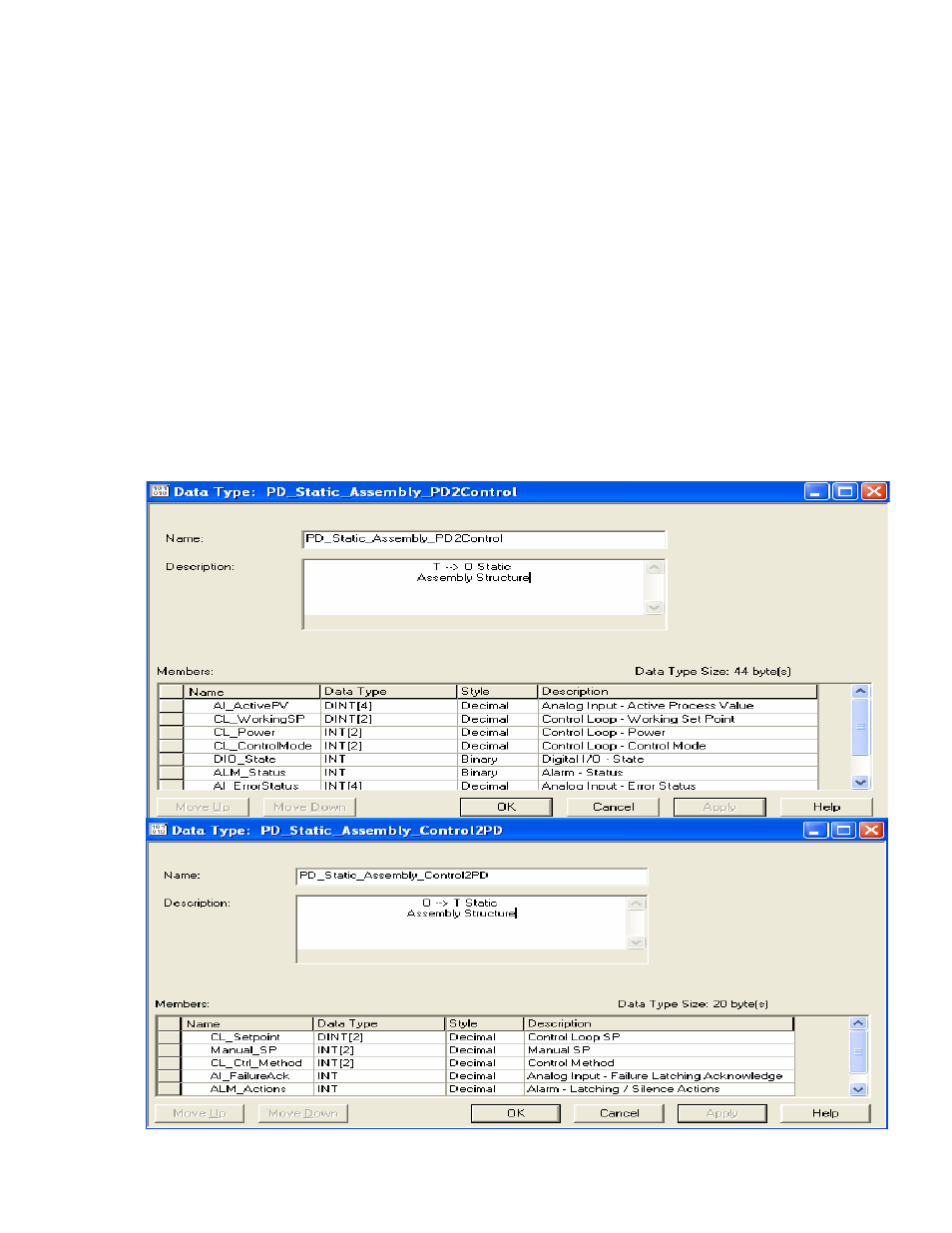
transfer of data to and from the controller to the various PD assemblies. To
accomplish this, user defined data types were created for the purpose of reflecting the
O
Æ T and the T Æ O assembly structures. In comparing the structure of the screen
shot below with the tables found in sections 2.2.1 and 2.2.3 you will see a close
resemblance. In taking a closer look, you will see that each of the members in both
data types T
Æ O and the O Æ T, correspond directly to the above mentioned tables.
Figure 3.1c
160