Control loops, Loop settings – Watlow Series PD User Manual
Page 37
W a t l o w S e r i e s P D
■
35
■
C h a p t e r 7 C o n f i g u r a t i o n P a g e
Control Loops
The Control Loops folder contains folders and links for configuring the control loops installed in the Series PD.
The controller leaves the factory with default settings on the Loop Setting page that disable all output functions. To
get the Series PD operational, you must go through the Loop Settings links and set up the control loops. The Loop
folder links are:
•
Loop Settings
•
Multiple PID Sets
Note: Loop 2 folder appears on dual channel models only.
Loop Settings
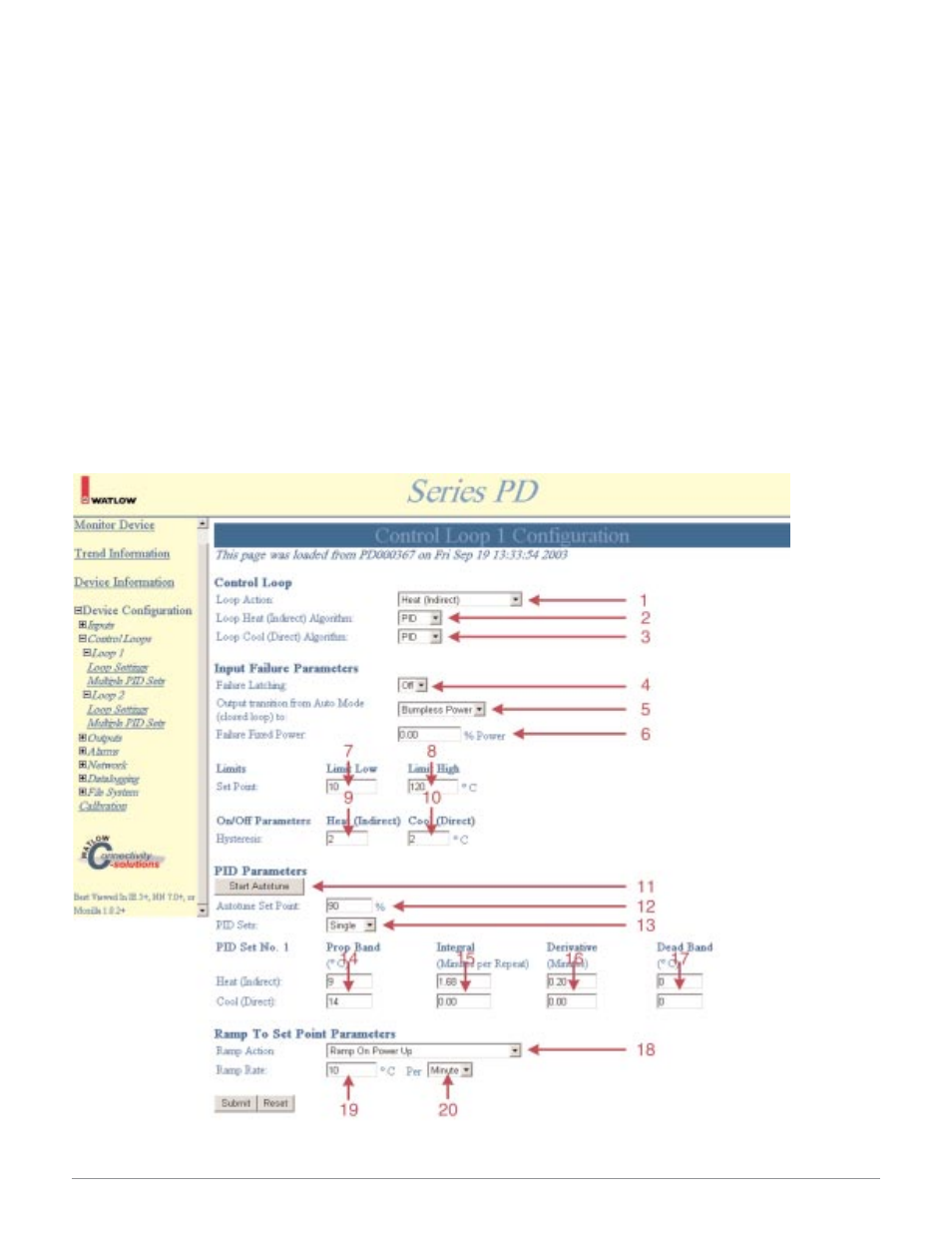
The Control Loop Configuration page sets the parameters for the control loops installed. The control loop func-
tions, input failure parameters, set point limits, on/off parameters, autotune start/stop, PID parameters and ramp
to set point settings are configured on this page.
You can see and change all of the parameters on the Control Loop Configuration page. Only those that apply
will be relevant. For example, you can set the On/Off Hysteresis even though you have the Loop Algorithms set to
PID control. Only parameters relating to PID have any effect on the controller. If you change the Loop Algorithm to
On/Off, the hysteresis values previously entered are used.
Note: You must click Submit to send the new values to the Series PD.
Figure 35 — Control Loop Configuration Web Page Example
Note: Red tag arrows and tag numbers are links to item descriptions. Click on a red tag arrow or number to go to a description of the item.