W a t l o w S e r i e s P D
■
30
■
C h a p t e r 7 C o n f i g u r a t i o n P a g e
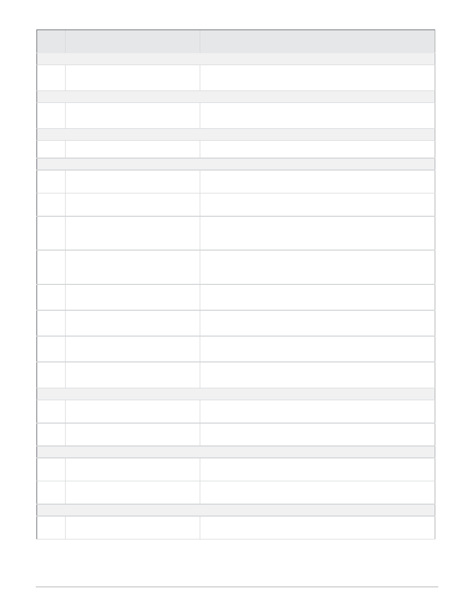
Figure 30 — Analog Input Web Page Tag Descriptions
Tag #
Analog Input
Configuration Parameters
Parameter Description
Analog Input
1.
Sensor Type
Selects the analog input sensor type. Off (disabled), thermocouple,
RTD, voltage process, current process or INFOSENSE PnP
Thermocouple Parameters
2.
Thermocouple Type
Selects the analog input thermocouple linearization. Type J, K, B,
T, E, N, C, D, PTII, R or S.
RTD Parameters
3.
RTD Curve
Sets the RTD calibration curve. DIN curve only.
Process Parameters
4
.
Process Precision
Sets the decimal position for the process input. 0, 0.0, 0.00 or
0.000.
5.
Process Units
Selects the units label displayed on the web page. Up to four al-
pha- numeric characters.
6.
Low Process Scale
Sets the low scale value for the process input signal. For example,
if you want 4-20 mA to represent 0 to 100%RH, set low process
scale to 0.
7.
High Process Scale
Sets the high scale value for the process input signal. For exam-
ple, if you want 4-20 mA to represent 0 to 100%RH, set high
process scale to 100.
8.
Low Voltage Scale
Sets the low range value for the voltage input signal. For example,
if you need 1-5 Vdc, set low voltage scale to 1.
9.
High Voltage Scale
Sets the high range value for the voltage input signal. For exam-
ple, if you need 1-5 Vdc, set high voltage scale to 5.
10.
Low Current Scale
Sets the low range value for the current input signal. For exam-
ple, if you need 4-20 mA, set low current scale to 4.
11.
High Current Scale
Sets the high range value for the current input signal. For exam-
ple, if you need 4-20 mA, set high current scale to 20.
Temperature Process Value Configuration
12.
Temperature Process
Value Units
Sets the temperature measurement units. Celcius or Fahrenheit.
13.
Temperature Process
Value Precision
Selects the decimal location for temperature inputs. 0 or 0.0.
Input Filtering
14.
Filter Method
Selects the filtering action for the input signal. Off (disabled) or
First Order.
15.
Filter Time Base
Sets the time constant for the first order filter. 0.1 to 60.0 seconds.
Offsets
16.
Single Offset Value
Shifts the input signal up or down.