On-off control, Proportional control – Watlow Series PD User Manual
Page 135
To set the input error failure mode, go to Device
Configuration > Control Loops > Loop 1 or 2 >
Loop Settings > Input Failure Parameters. These
settings determine controller operation in the event of a
sensor failure. You can choose to have the controller
perform a “bumpless” transfer, switch power to output a
preset manual power level, or turn the output power off.
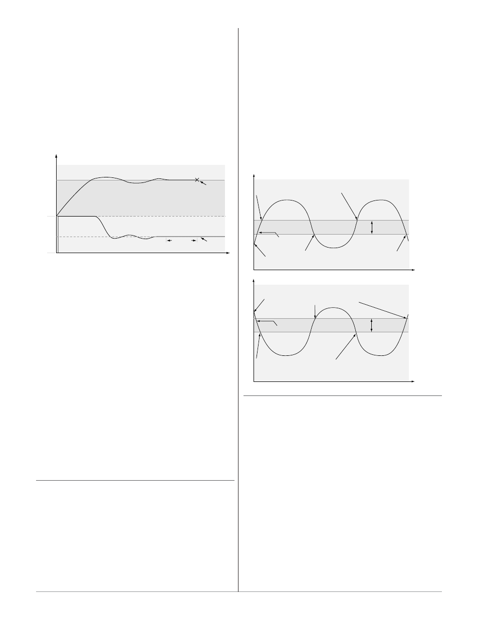
Bumpless transfer will allow the controller to trans-
fer to the manual mode using the last power value cal-
culated in the auto mode, if the process was stable at a
±5 percent output power level for two minutes prior to
sensor failure, and the power level is less than 75 per-
cent.
To determine the controller’s response once a valid
input signal returns to the controller, go to Device
Configuration > Control Loops > Loop 1 or 2 >
Loop Settings > Input Failure Parameters > Fail-
ure Latching. If you want any input errors to latch,
set Failure Latching to On. With this setting the con-
troller will continue to indicate an input error until the
error is manually cleared. To clear a latched error, go to
Monitor Device > Process Value > Status and click
the Acknowledge button.
If Failure Latching is set to off, the controller will
automatically clear the input error, change the Status
back to No Fault and return to reading the tempera-
ture. If the controller was in the auto mode when the in-
put error occurred, it will return to auto mode and re-
sume closed loop control. If the controller was in manu-
al mode when the error occurred, the controller will re-
main in open loop control.
To view or change the control mode of operation, go
to Monitor Device > Control Loop Status > Mode
and select Off (control loop outputs disabled), Manual
(open loop) or Auto (closed loop).
On-Off Control
On-off control switches the output either full on or
full off, depending on the input, auto set point and hys-
teresis values. The hysteresis value indicates the
amount the process value must deviate from the set
point to turn on the output. Increasing the value de-
creases the number of times the output will cycle. De-
creasing hysteresis improves controllability. With hys-
teresis set to 1, the process value would stay closer to
the auto set point, but the output would switch on and
off more frequently, and may result in the output “chat-
tering.”
To select On-off control, go to Device Configura-
tion > Control Loops > Loop 1 or 2 > Loop Settings
> Loop Heat Algorithm or Loop Cool Algorithm
and select On/Off.
To adjust the hysteresis, go to Device Configura-
tion > Control Loops > Loop 1 or 2 > Loop Settings
> On/Off Parameters > Heat (Indirect) or Cool (Di-
rect). Enter a value for hysteresis and click the Submit
button to send the new value.
NOTE: Input Error Failure Parameters have no effect in on-off control
mode. The control outputs go off.
Proportional Control
Some processes need to maintain a temperature or
process value closer to the set point than on-off control
can provide. Proportional control provides closer control
by adjusting the output when the temperature or
process value is within a proportional band. When the
value is in the band, the controller adjusts the output
based on how close the process value is to the set point.
The closer the process value is to the set point, the low-
er the output power. This is similar to backing off on
the gas pedal of a car as you approach a stop sign. It
keeps the temperature or process value from swinging
as widely as it would with simple on-off control. Howev-
er, when the system settles down, the temperature or
process value tends to “droop” short of the set point.
With proportional control the output power level
equals (set point minus process value) divided by the
proportional band value.
Set Point
Time
Te
mperature
The heating action switches off when the process
temperature rises above the set point.
The heating action
switches on at startup.
Hysteresis
Process Temperature
Hysteresis
Time
Te
mperature
The cooling action
switches
on at startup.
Process Temperature
The cooling action switches on when
the process temperature rises above
the set point plus the hysteresis.
Set Point
The heating action switches on when the process temperature
drops below the set point minus the hysteresis.
The cooling action switches off when the process
temperature drops below the set point.
Time
Temperature
40%
Sensor
Break
2 minutes
Locks in
Output
Power
0%
Set Point
Actual Temperature
Output Power
Power
100%
W a t l o w S e r i e s S D
■
1 3 3
■
C h a p t e r 1 0 F e a t u r e s