Alarms, Process or deviation alarms, Process alarms – Watlow Series PD User Manual
Page 138: Deviation alarms
Alarms
Alarms are activated when the process value or tem-
perature leaves a defined range. A user can configure
how and when an alarm is triggered, what action it
takes and whether it turns off automatically when the
alarm condition is over.
To configure an output as an alarm output , go to
Device Configuration > Output 1, 2, 3 or 4 > Out-
put Function and select Event. Click the Submit but-
ton to send the new value.
Process Alarms
A process alarm uses an absolute set point to define
the alarm condition. The alarm set point is independent
from the auto set point.
To configure an event output as a process alarm, go
to Device Configuration > Alarm 1, 2, 3, 4, 5, 6, 7 or
8 > Alarm Type and select Low Process or High
Process. Click the Submit button to send the new value.
The high process alarm set point defines the process
value or temperature that triggers a high side alarm. It
must be between the low and high values of the sensor
range.
The low process alarm set point defines the process
or temperature that triggers a low side alarm. It must
be between the low and high values of the sensor range.
To view or change a Process Alarm Set Point, go to
Monitor Device > Alarm Status > Alarm 1, 2, 3, 4, 5,
6, 7 or 8 Set Point. Enter the Alarm Set Point value
and click the Submit button to send the new value.
or
Go to Device Configuration > Alarm 1, 2, 3, 4, 5,
6, 7 or 8 > Process Alarm Parameters. Enter the
Alarm Set Point value and click the Submit button to
send the new value.
Deviation Alarms
The deviation alarm functions of the Series PD are a
bit different from other Watlow controllers. These new
functions, along with the ability to apply basic logic
functions to the alarms, provide new alarm capabilities
not available on previous products.
Deviation alarms use a set point that is defined rela-
tive to the auto set point. Low or high deviation alarm
set points are calculated by adding or subtracting offset
values from the auto set point. If the auto set point
changes, the trip point defined by the deviation alarm
set point automatically changes with it.
To configure an event output as a deviation alarm,
go to Device Configuration > Alarm 1, 2, 3, 4, 5, 6, 7
or 8 > Alarm Type and select Low Deviation or High
Deviation. Click the Submit button to send the new val-
ue.
The high deviation alarm set point defines the maxi-
mum deviation from the auto set point that triggers a
high side alarm.
To calculate the high deviation alarm trip point:
Auto Set Point + High Deviation Alarm Set Point =
High Deviation Alarm Trip Point.
A positive value results in a trip point above the auto
set point and a negative value results in a trip point below
the auto set point.
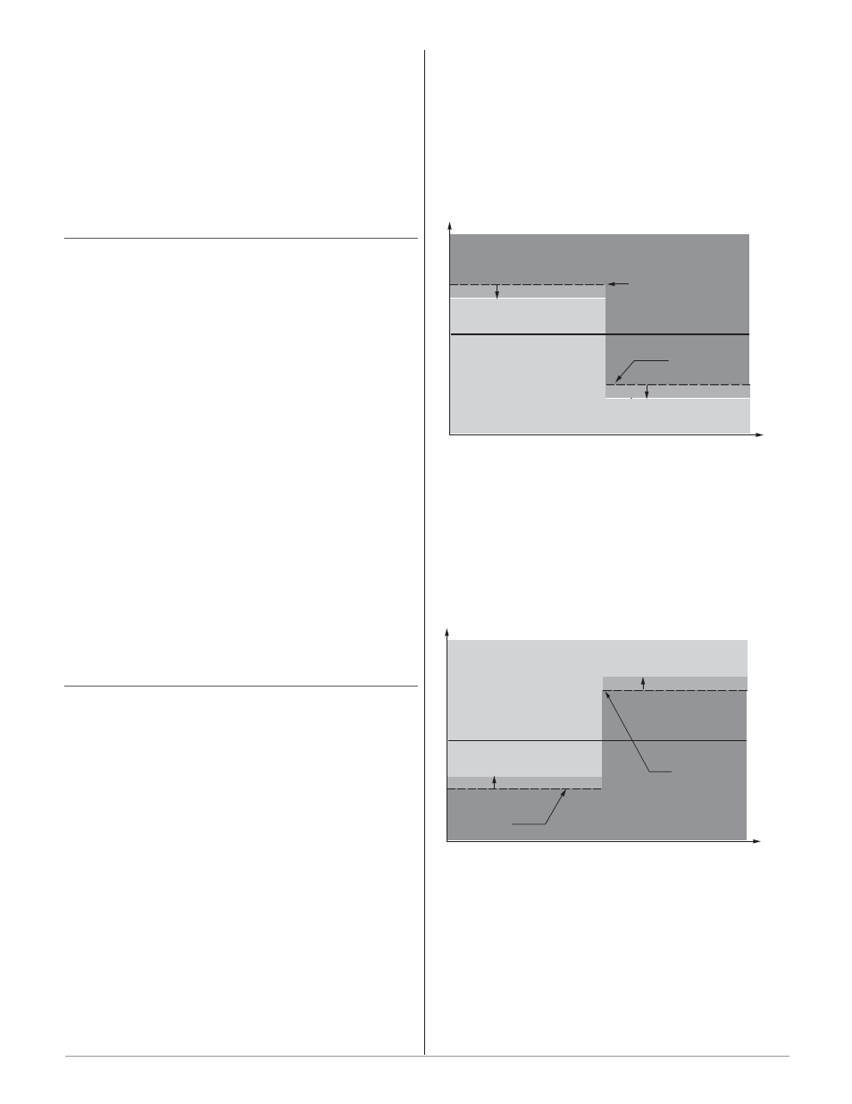
The low deviation alarm set point defines the maxi-
mum deviation from the auto set point that triggers a
low side alarm.
To calculate the low deviation alarm trip point:
Auto Set Point - Low Deviation Alarm Set Point =
Low Deviation Alarm Trip Point.
A positive value results in a trip point below the au-
to set point and a negative value results in a trip point
above the auto set point.
To view or change a Deviation Alarm Set Point, go to
Monitor Device > Alarm Status > Alarm 1, 2, 3, 4, 5,
6, 7 or 8 Set Point. Enter the Alarm Set Point value
and click the Submit button to send the new value.
or
Go to Device Configuration > Alarm 1, 2, 3, 4, 5,
6, 7 or 8 > Process Alarm Parameters. Enter the
Alarm Set Point value and click the Submit button to
send the new value.
Set Point 100˚
Low Deviation Alarm
Set Point 10˚
Time
Temperature
Alarm Inactive
Alarm Hysteresis
Alarm Hysteresis
Low Alarm
Active at 90˚
Low Deviation Alarm
Set Point -10˚
Low Alarm
Active at 110˚
SP - LDA = Alarm Trip Point
100˚ - 10˚ = 90˚
100˚ - (-10) = 110˚
Set Point 100˚
High Deviation Alarm
Set Point 10˚
Alarm active at 110˚
Alarm Low Set Point 10˚
Time
Temperature
High Deviation Alarm
Set Point -10˚
Alarm Inactive
Alarm Hysteresis
Alarm Hysteresis
Alarm active at 90˚
SP + HDA = Alarm Trip Point
100˚ + (-10˚) = 90˚
100˚ + 10˚ = 110˚
W a t l o w S e r i e s P D
■
1 3 6
■
C h a p t e r 1 0 F e a t u r e s