1 attribute controller index/data, 2 ega palette, Attribute controller index/data – AMD Geode LX [email protected] User Manual
Page 379: Attribute controller index/data/data, Ega palette
AMD Geode™ LX Processors Data Book
379
Display Controller Register Descriptions
33234H
6.6.21.1 Attribute Controller Index/Data
The attribute controller registers do not have a separate address for writing index and data information. Instead, an internal
flip-flop alternates between index and data registers. Reading Input Status Register 1 (3BAh or 3DAh) clears the flip-flop to
the index state. The first write to 3C0h following a read from Input Status Register 1 will update the index register. The next
write will update the selected data register. The next write specifies a new index, etc.
6.6.21.2 EGA Palette
Index Address
3C0h
Data Address
3C1h (R)
3C0h (W)
Type
R/W
Reset Value
xxh
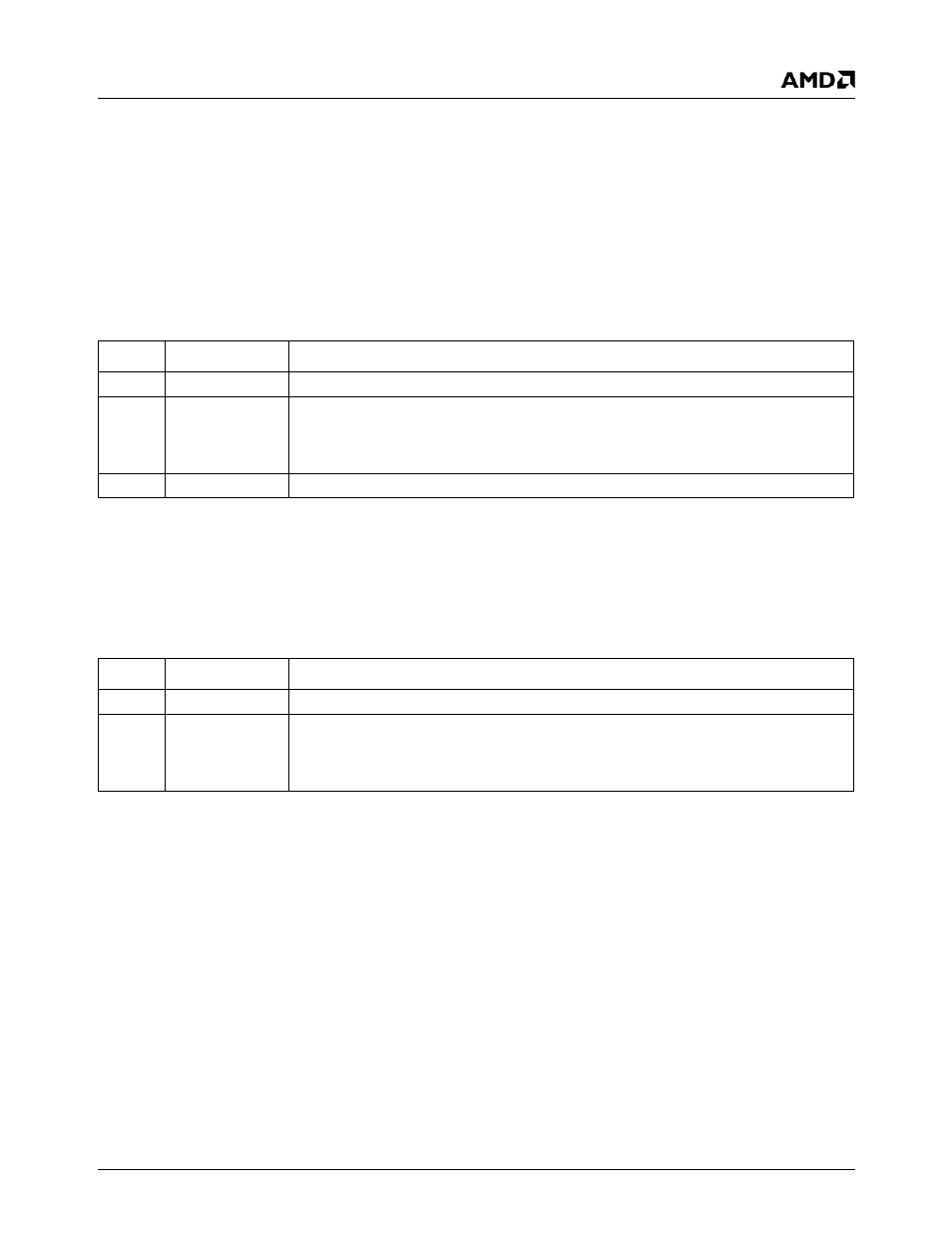
Attribute Controller Index Register Bit Descriptions
Bit
Name
Description
7:6
RSVD
Reserved.
5
INT_PAL_AD
Internal Palette Address. This bit determines whether the EGA palette is addressed by
the video pixel stream (bit = 1) or by the Attribute Controller Index register (bit = 0). This
bit should be set to 1 for normal VGA operation. CPU I/O accesses to the palette are dis-
abled unless this bit is a 0.
4:0
DATA_RG_INX
Data Register Index. This field addresses the individual palette and data registers.
Index
00h-0Fh
Type
R/W
Reset Value
xxh
EGA Palette Register Bit Descriptions
Bit
Name
Description
7:6
RSVD
Reserved.
5:0
COL_VAL
Color Value. Each of these 16 registers is used to expand the pixel value from the frame
buffer (one, two, or four bits wide) into a 6-bit color value that is sent the video DAC. The
EGA palette is “programmed out of the way” in 256 color mode. These registers can only
be read or written when the Internal Palette Address bit in the Index register (3C0h) is 0.