AMD Geode LX CS5536 User Manual
Amd geode™ lx processor ddr2 bios porting guide, 0 scope, 0 description
46959A - March 2009
1
AMD Geode™ LX Processor
DDR2 BIOS Porting Guide
1.0 Scope
The AMD Geode™ LX processor has an integrated DDR
memory controller. Due to the concerns over the availability
and increasing cost of DDR, AMD has developed a method
for operating DDR2 memory with the processor’s memory
controller. This application note details the software
changes necessary to enable this technology.
Note:
The solution described in this document does not
conform to the JEDEC DDR2 Specification. This
solution may not work with all DDR2 memory.
Note:
This is revision B of this document. The change
from revision A (also dated March 2009) is “AMD
Confidential” was removed.
2.0 Description
Initializing DDR2 SDRAM requires writing to additional
mode registers. In addition to the Mode Register (MR) and
Extended Mode Register (EMR), DDR2 defines two new
Extended Mode Registers, EMR(2) and EMR(3). The EMR
is renamed as EMR(1). Furthermore, the MR and EMR
definitions are not an exact match between DDR and
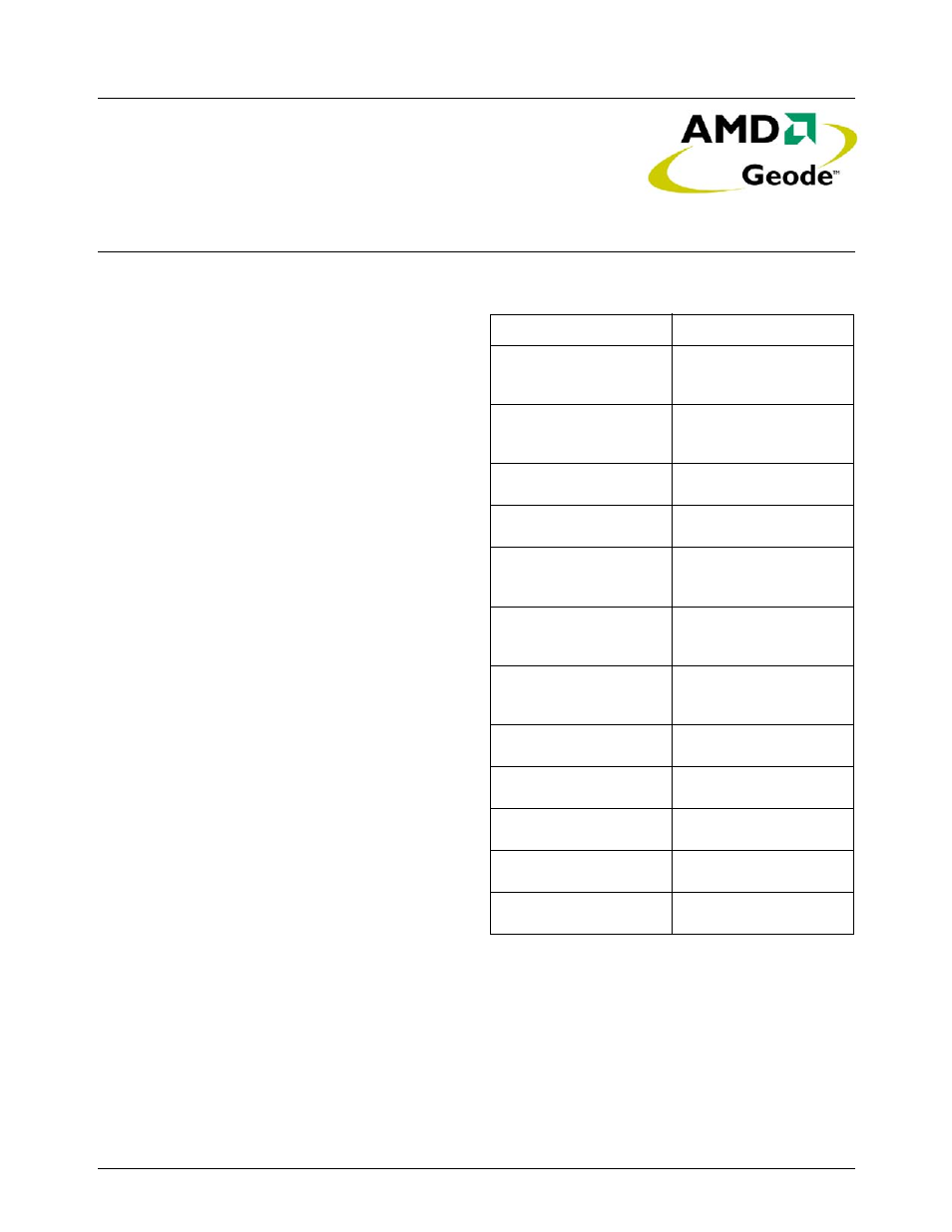
DDR2. Table 2-1 shows a comparison of the typical initial-
ization steps for DDR vs. DDR2.
Addressing MR vs. EMR(1), EMR(2) or EMR(3) is deter-
mined by the states of BA[2:0] while the LOAD MODE com-
mand is presented on the control signals. The data written
to the registers is the pattern presented on A[15:0] when
the command is initiated. (Note, however, that A[15:13]=0,
and BA[2]=0 in all cases.)
Software on the LX processor issues LOAD MODE com-
mands by writing the MC_CF07_DATA register. During the
operation, the memory controller (MC) uses various bits
and fields in the MC_CF07_DATA and MC_CF8F_DATA
registers. With the available settings, the LX processor is
not capable of generating the necessary signal patterns for
all the required LOAD MODE commands.
Table 2-1. Initialization Steps
DDR
DDR2
Wait a minimum of 200µs
after clocks and power are
stable, then assert CKE.
Wait a minimum of 200µs
after clocks and power are
stable, then assert CKE.
Wait a minimum of 400ns,
then issue a PRE-
CHARGE ALL command.
Wait a minimum of 400ns,
then issue a PRE-
CHARGE ALL command.
Issue a LOAD MODE
command to EMR(2)
Issue a LOAD MODE
command to EMR(3).
Issue a LOAD MODE
command to EMR to
enable the DLL.
Issue a LOAD MODE
command to EMR(1) to
enable the DLL.
Issue LOAD MODE com-
mand to MR with DLL
reset.
Issue LOAD MODE com-
mand to MR with DLL
reset.
Wait at least 200 clock
cycles. Issue a PRE-
CHARGE ALL command.
Wait at least 200 clock
cycles. Issue a PRE-
CHARGE ALL command.
Issue two REFRESH
commands.
Issue two REFRESH
commands.
Issue LOAD MODE to MR
without DLL reset.
Issue LOAD MODE to MR
without DLL reset.
Issue LOAD MODE to
EMR(1) with OCD default.
Issue LOAD MODE to
EMR(1) with OCD exit.
SDRAM initialization is
complete.
SDRAM initialization is
complete.