1 geodelink™ memory controller, Geodelink™ memory controller, Figure 6-2 – AMD Geode LX [email protected] User Manual
Page 210: Glmc block diagram
210
AMD Geode™ LX Processors Data Book
GeodeLink™ Memory Controller
33234H
6.1
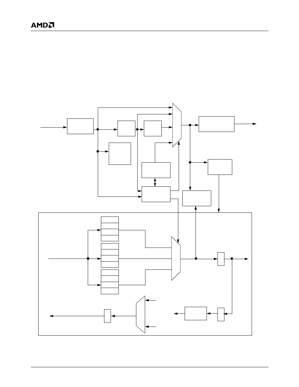
GeodeLink™ Memory Controller
The GeodeLink™ Memory Controller (GLMC) module sup-
ports the Unified Memory Architecture (UMA) of the
AMD Geode™ LX processor and controls a 64-bit DDR
SDRAM interface without any external buffering. The inter-
nal block diagram of the GLMC is shown in Figure 6-2.
The SDRAM memory array contains both the main system
memory and the graphics frame buffer. Up to four module
banks of SDRAM are supported. Each module bank can
have two or four component banks depending on the mem-
ory size and organization. The maximum configuration is
four module banks with four component banks, each pro-
viding a total of 16 open banks with the maximum memory
size supported being 2 GB.
The GLMC handles multiple requests for memory data
from the CPU Core, the Graphics Processor, the Display
Controller, and the external PCI bus via the GeodeLink
Interface Units (GLIUs). The GLMC contains extensive
buffering logic that helps minimize contention for memory
bandwidth between the various requests.
Figure 6-2. GLMC Block Diagram
Adrs/Ctl
Gen
Req
Req
Refresh
Arbiter
Data
Control
SDRAM IF
MSR
Registers
W_DATA
Write
Response
MSR
Rd Resp
Data Path
RAS
CAS
WE
CKE
MA
BA
CS
DQ
DQM
DQS
Bank/
Page
Logic
Buf
Buf
R_DATA
MemRd
Response
GLUI0
Request
Packet
GLUI0
Write
Packet
GLUI0
Response
Packet
Write
Buf
Write
Buf
Write
Buf
Capture/
Resync