6 dc vbi pitch and size (dc_vbi_pitch), 12 color key control registers, 1 dc color key (dc_clr_key) – AMD Geode LX [email protected] User Manual
Page 347: 0b4h, Dc vbi pitch and size (dc_vbi_pitch), Xxxxxxxxh, 0b8h, Dc color key (dc_clr_key), 00000000h
AMD Geode™ LX Processors Data Book
347
Display Controller Register Descriptions
33234H
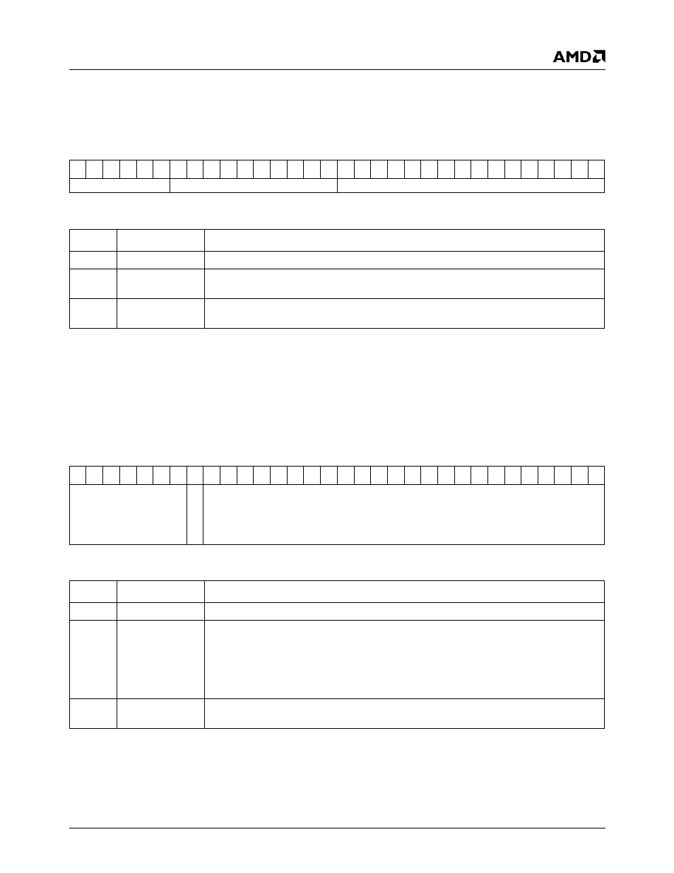
6.6.11.6 DC VBI Pitch and Size (DC_VBI_PITCH)
6.6.12
Color Key Control Registers
6.6.12.1 DC Color Key (DC_CLR_KEY)
DC Memory Offset 0B4h
Type
R/W
Reset Value
xxxxxxxxh
DC_VBI_PITCH Register Map
31 30 29 28 27 26 25 24 23 22 21 20 19 18 17 16 15 14 13 12 11 10
9
8
7
6
5
4
3
2
1
0
RSVD
VBI_Size
VBI_Pitch
DC_VBI_PITCH Bit Descriptions
Bit
Name
Description
31:26
RSVD
Reserved. Set to 0.
25:16
VBI_SIZE
VBI Data Size. Indicates how many QWORDs of data to fetch from memory for each line
of VBI
15:0
VBI_PITCH
VBI Data Pitch. Indicates how many QWORDs of memory space to increment when
moving from the start of one active VBI line to the start of the next.
DC Memory Offset 0B8h
Type
R/W
Reset Value
00000000h
DC_
CLR_KEY
Register Map
31 30 29 28 27 26 25 24 23 22 21 20 19 18 17 16 15 14 13 12 11 10
9
8
7
6
5
4
3
2
1
0
RSVD
C
L
R_KEY_EN
CLR_KEY
DC_CLR_KEY Bit Descriptions
Bit
Name
Description
31:25
RSVD
Reserved. Set to 0.
24
CLR_KEY_EN
Color Key Enable. This bit enables color key detection in the DC. When this bit is set,
the DC adjusts the alpha value of pixels whose 24-bit RGB values match the value in
CLR_KEY (bits [23:0]). A mask is also provided in CLR_KEY_MASK (DC Memory Offset
0BCh[23:0]) to indicate which bits can be ignored when performing this match. Color key
detection is performed after the data has been decompressed and the cursor has been
overlayed, but before scaling and filtering take place.
23:0
CLR_KEY
Color Key. This field represents the RGB value that will be compared to DC pixels when
performing color key detection.