AMD Geode LX [email protected] User Manual
Page 407
AMD Geode™ LX Processors Data Book
407
Video Processor
33234H
Maximum Frequency
The FP will operate at a DOTCLK frequency of up to 170
MHz. There is no minimum frequency; however, many flat
panels have signal timings that require minimum frequen-
cies. Refer to the flat panel display manufacturer’s specifi-
cations as appropriate.
CRC Signature
The FP contains hardware/logic that performs Cyclical
Redundancy Checks (CRCs) on the digital video/graphics
pipeline. This feature is used for error detection and makes
it possible to capture a unique 24-or 32-bit signature for
any given mode setup. An error in the video/graphics mem-
ory interface, control logic, or pixel pipeline will produce a
different signature when compared to a known good signa-
ture value. This allows the programmer to quickly and
accurately test a video screen without having to visually
inspect the screen for errors. By default, a 24-bit signature
generator is used. For more accuracy, a 32-bit signature
generator my be selected.
Dithering
After the video mixer gamma RAM logic, the graphic data
or the video data goes through the dithering logic.
Some panels have limitations of supporting maximum num-
ber of bits to display all color shades that the CRT monitor
can support. For example, if the selected mode is 24-bpp
and the panel can support only 18-bpp, the remaining two
bits for each color is used for dithering to get the desired
number of shades as compared to the CRT.
The idea behind dithering is to achieve intermediate color
intensities by allowing the human eye to blend or average
the intensities of adjacent pixels on a screen. Intensity res-
olution is gained by sacrificing spatial resolution.
For example, consider just the red color component of a
2x2 square of pixels. If the only two options for the red color
component were to be turned on or off, then there would
only be two colors, black and the brightest red. However, if
two of the pixels’ red color components in the 2x2 square
were turned on and two were turned off, the human eye
would blend these adjacent pixels and the 2x2 pixel square
would appear to be half as bright as the brightest red. The
drawback is that fine details and boundaries between
regions of differing color intensities become slightly blurred.
The FP supports dithering patterns over an 8x8 pixel area.
An 8x8 pixel area supports 64 different dithering patterns.
This means that the 8-bit input intensity for a given pixel pri-
mary color component can be reduced down to its two
most significant bits by using the six least significant bits to
select a 8x8 pixel pattern whose average intensity is equal
to the original 8-bit input intensity value.
As an example, consider a display screen that is capable of
producing six different intensities of the red color compo-
nent for each pixel. Given an 8-bit red intensity value,
01010110, the problem is to come up with a 8x8 pixel pat-
tern, using only the six available red pixel intensities, that
when averaged together, yield the value of the original 8-bit
intensity.
The values of the six available intensities, padded out to
eight bits, are 00000000, 01000000, 01010000, 10000000,
11000000, and 11010000. The given intensity, 010110, lies
between 01000000 and 10000000, so these two intensities
are used in the 8x8 pixel pattern, as shown in Figure 6-37
on page 408. The average intensity of this 8x8 pattern is
01010110.
The actual dithering pattern is an 8x8 pattern of 1s and 0s.
A 0 in a given position of the pattern indicates that the trun-
cated value of the input color component intensity be used.
A 1 means use the next higher truncated value. In the pre-
vious example, the intensity value was 01010110, the trun-
cated value is 01000000 (least significant six bits set to 0),
and the next higher truncated value is 10000000.
The 8x8 dithering pattern for an input intensity value whose
least significant six bits are already zero is made up of all
0s. This means that the next higher truncated intensity
value is never used because the input intensity value is the
same as its truncated value. As the value of the least signif-
icant six bits of the input intensity value increases, the input
intensity value gets closer to the next higher truncated
intensity value, and more 1s are added to the pattern. For
example, when the value of the least significant six bits of
the input intensity value is 16, there will be sixteen 1s in the
dithering pattern and the next higher truncated intensity
value will be used sixteen times within the 8x8 pattern.
DOTCLK
CLK
CLK
CLK
CLK
CLK
HSYNC
HSYNC
HSYNC
HSYNC
HSYNC
HSYNC
VSYNC
VSYNC
VSYNC
VSYNC
VSYNC
VSYNC
LDEMOD
LDE
LDE
LDE
LDE
LDE
VDDEN
ENLVDD
ENLVDD
ENLVDD
ENLVDD
ENLVDD
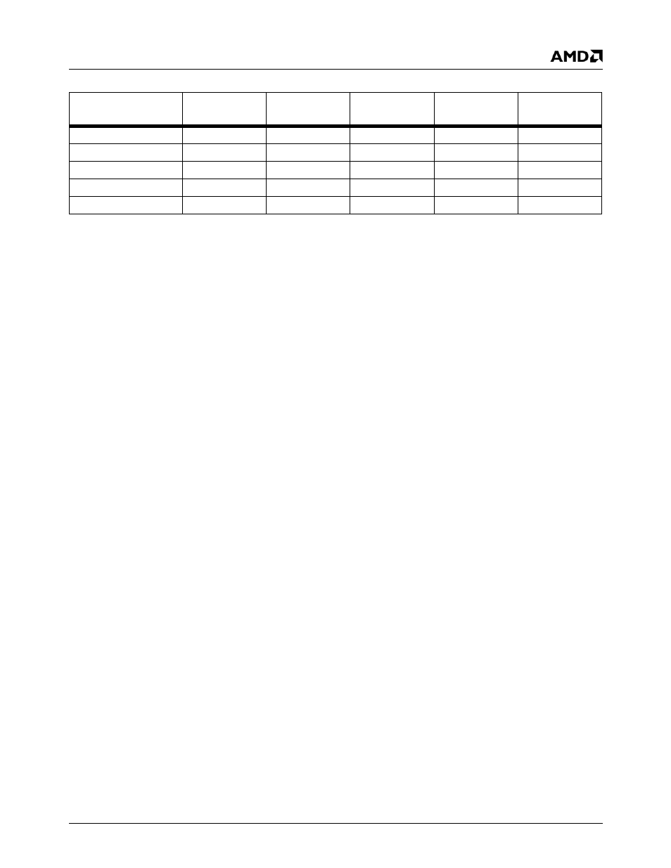
Table 6-66. Panel Output Signal Mapping (Continued)
Pin Name
TFT
9-Bit
TFT
18-Bit
TFT
24-Bit
TFT
9+9-Bit
TFT
12+12-Bit