5 dc crt vertical blank timing (dc_v_blank_timing), 6 dc crt vertical sync timing (dc_v_sync_timing), Dc crt vertical blank timing (dc_v_blank_timing) – AMD Geode LX [email protected] User Manual
Page 331: Dc crt vertical sync timing (dc_v_sync_timing)
AMD Geode™ LX Processors Data Book
331
Display Controller Register Descriptions
33234H
6.6.5.5
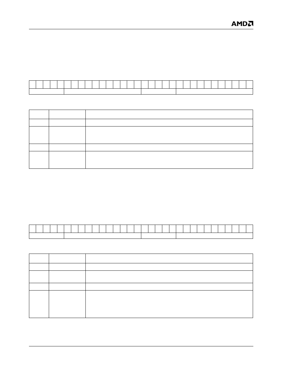
DC CRT Vertical Blank Timing (DC_V_BLANK_TIMING)
This register contains vertical blank timing information. All values are specified in lines. For interlaced display, no border is
supported, so blank timing is implied by the total/active timing.
6.6.5.6
DC CRT Vertical Sync Timing (DC_V_SYNC_TIMING)
This register contains CRT vertical sync timing information. All values are specified in lines.
DC Memory Offset 054h
Type
R/W
Reset Value
xxxxxxxxh
DC_V_BLANK_TIMING Register Map
31 30 29 28 27 26 25 24 23 22 21 20 19 18 17 16 15 14 13 12 11 10
9
8
7
6
5
4
3
2
1
0
RSVD
V_BLANK_END
RSVD
V_BLANK_START
DC_V_BLANK_TIMING Bit Descriptions
Bit
Name
Description
31:27
RSVD
Reserved. These bits should be programmed to zero.
26:16
V_BLANK_END
Vertical Blank End. This field represents the line at which the vertical blanking signal
becomes inactive minus 1. If the display is interlaced, no border is supported, so this
value should be identical to V_TOTAL.
15:11
RSVD
Reserved. These bits should be programmed to zero.
10:0
V_BLANK_
START
Vertical Blank Start. This field represents the line at which the vertical blanking signal
becomes active minus 1. If the display is interlaced, this value should be programmed to
V_ACTIVE plus 1.
DC Memory Offset 058h
Type
R/W
Reset Value
xxxxxxxxh
DC_V_SYNC_TIMING Register Map
31 30 29 28 27 26 25 24 23 22 21 20 19 18 17 16 15 14 13 12 11 10
9
8
7
6
5
4
3
2
1
0
RSVD
V_SYNC_END
RSVD
V_SYNC_START
DC_V_SYNC_TIMING Bit Descriptions
Bit
Name
Description
31:27
RSVD
Reserved. These bits should be programmed to zero.
26:16
V_SYNC_END
Vertical Sync End. This field represents the line at which the CRT vertical sync signal
becomes inactive minus 1.
15:11
RSVD
Reserved. These bits should be programmed to zero.
10:0
V_SYNC_
START
Vertical Sync Start. This field represents the line at which the CRT vertical sync signal
becomes active minus 1. For interlaced display, note that the vertical counter is incre-
mented twice during each line and since there are an odd number of lines, the vertical
sync pulse will trigger in the middle of a line for one field and at the end of a line for the
subsequent field.