2 vip control/configuration registers, 1 vip control register 1 (vip_ctl_reg1), Vip control register 1 (vip_ctl_reg1) – AMD Geode LX [email protected] User Manual
Page 488
488
AMD Geode™ LX Processors Data Book
Video Input Port Register Descriptions
33234H
6.10.2
VIP Control/Configuration Registers
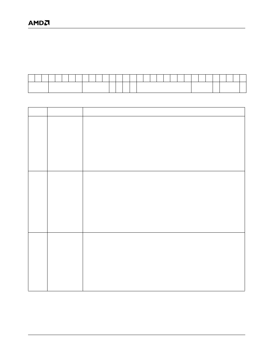
6.10.2.1 VIP Control Register 1 (VIP_CTL_REG1)
VIP Memory Offset 00h
Type
R/W
Reset Value
42000001h
VIP_CTL_REG1 Register Map
31 30 29 28 27 26 25 24 23 22 21 20 19 18 17 16 15 14 13 12 11 10
9
8
7
6
5
4
3
2
1
0
ANC_FF
VID_FF
ERR_DETECT NI MB DZ DD
DT_EN
RUN_MODE P VIP_MODE
VRST
VIP_CTL_REG1 Bit Descriptions
Bit
Name
Description
31:29
ANC_FF
Ancillary FIFO Flush. Watermark level for flushing the 64-deep ancillary FIFO. This
value determines how full the ancillary FIFO is before VIP starts writing QWORDs to sys-
tem memory. If the FIFO has greater than 4 QWORDs and the address is aligned, VIP
generates a burst (4 QWORDs) transaction.This value is reset to 2 (flush when 17
QWORDs).
0: Flush when there is at least 1 QWORD.
1: Flush when there are at least 9 QWORDs.
2: Flush when there are at least 17 QWORDs. (Default)
n: Flush when there are at least nx8 +1 QWORDs (up to n = 7x8 +1 = 57).
(ANC FIFO size is 64 QWORDs).
28:24
VID_FF
Video FIFO Flush. Watermark level for flushing the 64-deep (planar mode) or 192-deep
(linear mode) FIFO(s). This value determines how full the ancillary FIFO is before VIP
starts writing QWORDs to system memory. If the FIFO has greater than 4 QWORDs and
the address is aligned, VIP generates a burst (4 QWORDs) transaction. This value is
reset to 2 (flush when 17 QWORDs).
0: Flush when there is at least 1 QWORD.
1: Flush when there are at least 9 QWORDs.
2: Flush when there are at least 17 QWORDs. (Default)
n: Flush when there are at least nx8+1 QWORDs).
(FIFO size is 192 QWORDs in Linear mode, maximum value is 17H/23d).
(FIFO size is 64 QWORDs in Planar mode, maximum value is 7).
23:20
ERR_DETECT
Video Detection Enable. Selects what detection circuitry is used to detect loss of valid
video input. When an error is detected, the video_ok output is set low. The associated
interrupt pending bit must be cleared to allow the video_ok signal to return high.
Bit 23: Runaway Line Error Abort (aborts line if a line is detected longer then 3000
clocks).
Bit 22: Vertical Timing error (Vertical Count Register must be programmed) or address-
ing error (max_addr reg must be programmed).
Bit 21: Number of clocks per active line error (checks that each line has the same # of
data).
Bit 20: Loss of VIP clock (watchdog timer using GLIU clocks --128 GLIU clocks).