2 vip control register 2 (vip_ctl_reg2), Vip control register 2 (vip_ctl_reg2), 00000000h – AMD Geode LX [email protected] User Manual
Page 490
490
AMD Geode™ LX Processors Data Book
Video Input Port Register Descriptions
33234H
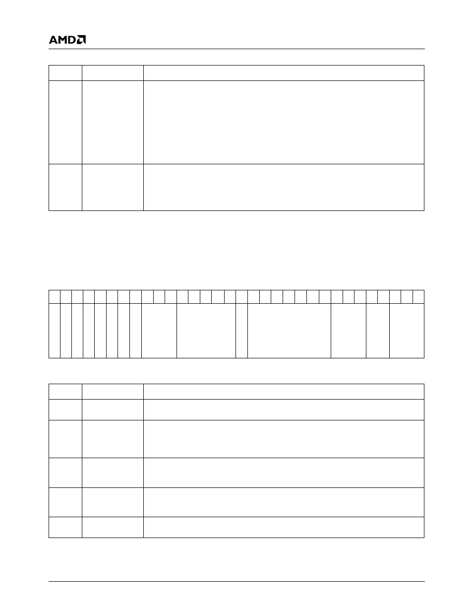
6.10.2.2 VIP Control Register 2 (VIP_CTL_REG2)
3:1
VIP_MODE
VIP Operating Mode.
000: IDLE. This mode forces VID[15:0] to 0 from pads to VIP.
001: VIP 2.0 8-bit mode.
010: VIP 2.0 16-bit.
011: VIP 1.1 8-bit.
100: Message Passing.
101: Data Streaming.
110: 601 type 8-bit mode.
111: 601 type 16-bit mode.
0
VRST
VIP Reset. When set to 1, this bit causes the VIP input logic to be reset. The control reg-
isters and base registers are not reset. Data is received/stored once this bit is set back to
0 according to Control Register 1 and 2. A 1 should also be written to the FIFO Reset
(Control Register 3 (VIP Memory Offset 2Ch[0])) between writing a 1 and 0 to this regis-
ter. The power-up value of VRST is 1.
VIP Memory Offset 04h
Type
R/W
Reset Value
00000000h
VIP_CTL_REG1 Bit Descriptions (Continued)
Bit
Name
Description
VIP_CTL_REG2 Register Map
31 30 29 28 27 26 25 24 23 22 21 20 19 18 17 16 15 14 13 12 11 10
9
8
7
6
5
4
3
2
1
0
FI
A_ERR
_
EN
R_
E
N
SW
C
ANC
1
0
ANC
P
E
N
LPB
FF
_R/W
PA
G
E
_
C
N
T
ANC_F
F
_T
HRESH
RSVD
VID
_
FF_THR
E
S
H
SYNC_T
O
_PIN
FIELD
_
T
O
_
D
C
SY
N
C
_T
O_DC
VIP_CTL_REG2 Bit Descriptions
Bit
Name
Description
31
FI
Field Invert. When set to 1, the polarity of the input field bit is inverted. This allows for
devices that violate the VIP 2.0 specification.
30
A_ERR_EN
Address Error Enable. When set to 1, the GLIU address that VIP is writing to is com-
pared to the Max Address register (VIP Memory Offset 14h). If a comparison is made, the
VIP Run Mode control is forced to 0 causing VIP to stop capturing data. The frame error
interrupt is generated.
29
R_EN
Repeat Flag Enable. When set to 1, the repeat flag in the SAV or EAV header is used to
determine if the packet is saved. This allows the VIP to drop repeat fields during 3:2 pull
down.
28
SWC
Sub-Window Capture Enable. When set to 1, only a portion of the frame/field is cap-
tured. Capture starts on the line specified in the Vertical Start/Stop register (VIP Memory
Offset 6Ch) and ends after the line specified in the Vertical Start/Stop register.
27
ANC10
10-bit Ancillary Data Input. When set to 1, ancillary data is received as 10-bit data.
(This is only applicable in 16-bit VIP mode).