Electrical specifications, 1 electrical connections, 1 pwr/gnd connections and decoupling – AMD Geode LX [email protected] User Manual
Page 597: 2 nc-designated balls, 3 unused inputs, 2 absolute maximum ratings, Electrical connections, Absolute maximum ratings, Table 7-1, 0 electrical specifications
AMD Geode™ LX Processors Data Book
597
7
Electrical Specifications
33234H
7.0
Electrical Specifications
This section provides information on electrical connections,
absolute maximum ratings, operating conditions, and
DC/AC characteristics for the AMD Geode™ LX processor.
All voltage values in the electrical specifications are with
respect to V
SS
unless otherwise noted.
7.1
Electrical Connections
7.1.1
PWR/GND Connections and Decoupling
Testing and operating the AMD Geode LX processor
requires the use of standard high frequency techniques to
reduce parasitic effects. When using this device, the effects
can be minimized by filtering the DC power leads with low-
inductance decoupling capacitors, using low-impedance
wiring, and by connecting all V
CORE,
V
IO
, V
MEM
, and ana-
log balls to the appropriate voltage levels.
7.1.2
NC-Designated Balls
Balls designated as NC (No Connection) should be left dis-
connected. Connecting an NC ball to a pull-up/-down resis-
tor, or an active signal could cause unexpected results and
possible circuit malfunctions.
7.1.3
Unused Inputs
All inputs not used by the system designer should be kept
at either ground or V
IO
. To prevent possible spurious opera-
tion. For active-high inputs to ground through a 20-k
Ω
(±10%) pull-down resistor and active-low inputs to V
IO
through a 20-k
Ω (±10%) pull-up resistor can be used if
desired.
7.2
Absolute Maximum Ratings
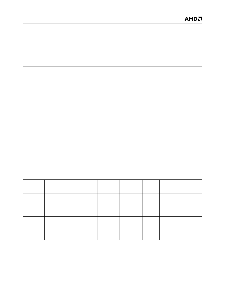
Table 7-1 lists absolute maximum ratings for the AMD Geode
LX processor. Stresses beyond the listed ratings may cause
permanent damage to the device. Exposure to conditions
beyond these limits may (1) reduce device reliability and (2)
result in premature failure even when there is no immedi-
ately apparent sign of failure. Prolonged exposure to condi-
tions at or near the absolute maximum ratings may also
result in reduced useful life and reliability. These are stress
ratings only and do not imply that operation under any con-
ditions other than those listed in Table 7-2 "Operating Con-
ditions" on page 598 is possible.
Table 7-1. Absolute Maximum Ratings
Symbol
Parameter
Min
Max
Unit
Comments
T
STORAGE
Storage Temperature
-65
150
°C
No Bias
V
CORE
Core Supply Voltage
1.5
V
V
IO
I/O Supply Voltage
3.0
3.6
V
Also applies to V
CA
, V
MA
,
V
VA
, and V
DAC
V
MEM
Memory Voltage
3.6
V
V
MAX
Voltage On Any Pin
-0.5
3.8
V
Except HSYNC, VSYNC
Voltage on HSYNC, VSYNC
-0.5
5.5
V
ESD - Human Body Model
2000
V
ESD - Machine Model
200
V