13 interrupt and genlock registers, 1 dc genlock control (dc_genlk_ctl), 0d4h – AMD Geode LX [email protected] User Manual
Page 350: Dc genlock control (dc_genlk_ctl), Xxxxxxxxh
350
AMD Geode™ LX Processors Data Book
Display Controller Register Descriptions
33234H
6.6.13
Interrupt and GenLock Registers
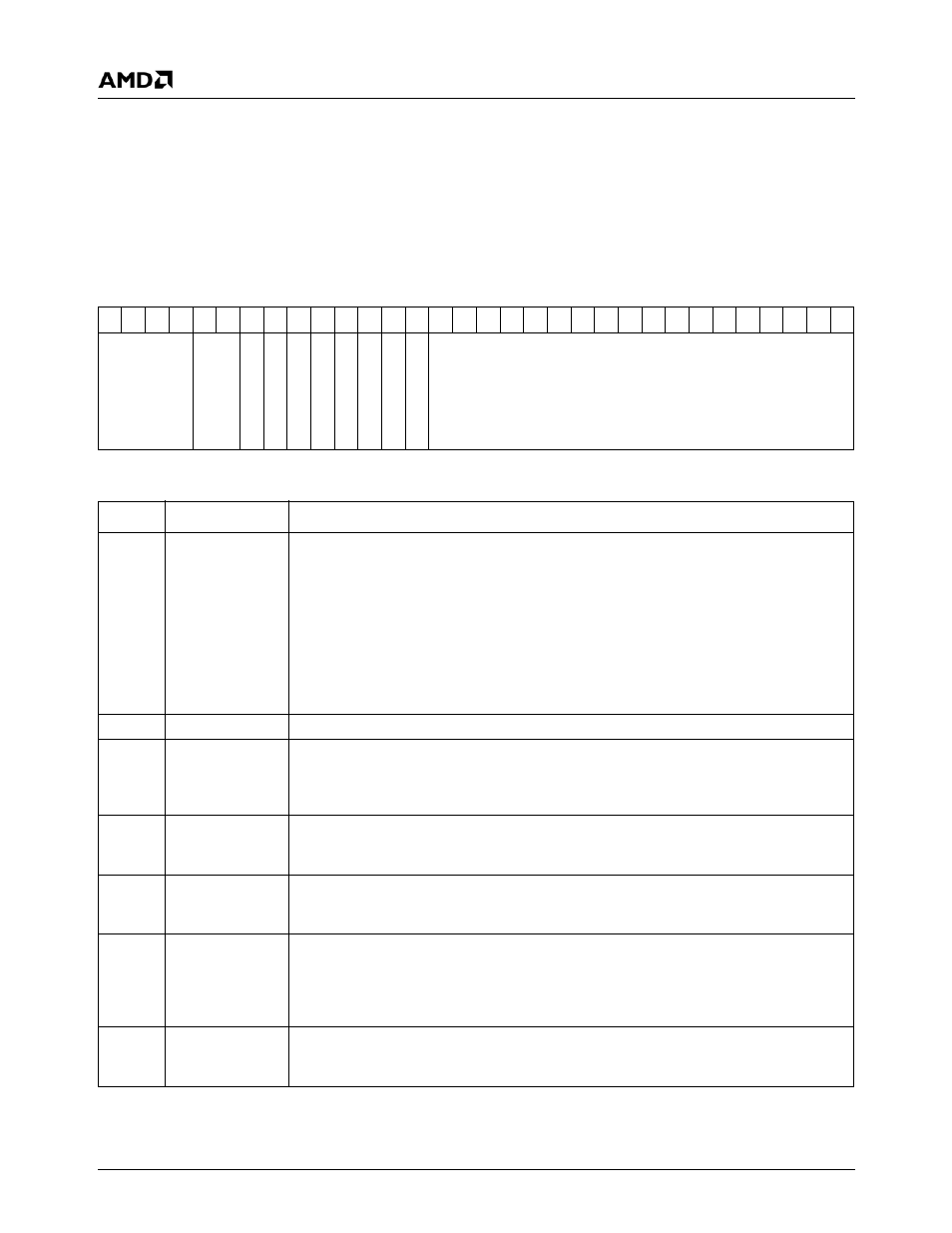
6.6.13.1 DC GenLock Control (DC_GENLK_CTL)
Settings written to this register do not take effect until the start of the frame or interlaced field after the timing register
update bit (DC Memory Offset 008h[6]) is set.
DC Memory Offset 0D4h
Type
R/W
Reset Value
xxxxxxxxh
DC_GENLK_CTL Register Map
31 30 29 28 27 26 25 24 23 22 21 20 19 18 17 16 15 14 13 12 11 10
9
8
7
6
5
4
3
2
1
0
FLICK_SEL
RSVD
ALPH
A
_
FLICK_EN
FL
ICK_EN
VIP_VIDEO_OK
GE
N
L
O
C
K_A
C
TIVE
SKEW
_W
A
IT
VIP_VSYNC_W
A
IT
GENLK_T
O
_EN
GENLK_EN
GENLK_SKW
DC_GENLK_CTL Bit Descriptions
Bit
Name
Description
31:28
FLICK_SEL
Flicker Filter Select. When the flicker filter is enabled (FLICK_EN, bit 24 = 1), this field
selects the weighting of the three taps in this vertical filter:
0000: 0, 1, 0 (top, middle, bottom)
0001: 1/16, 7/8, 1/16
0010: 1/8, 3/4, 1/8
0100: 1/4, 1/2, 1/4
0101: 5/16, 3/8, 5/16
All other combinations in this field are reserved.
27:26
RSVD
Reserved. Set to 0.
25
ALPHA_FLICK_
EN
Alpha Flicker Filter Enable. If set, this bit enables flicker filtering of the alpha value
when the flicker filter is enabled (FLICK_EN, bit 24 = 1). If the flicker filter is enabled and
this bit is cleared, the alpha value of the center pixel is passed through the flicker filter
unchanged.
24
FLICK_EN
Flicker Filter Enable. Enables the 3-tap vertical flicker filter (primarily used for interlaced
modes). When set, the graphics output is filtered vertically using the coefficients as indi-
cated in bits [22:21]. When clear, no flicker filtering is performed.
23
VIP_VIDEO_OK
(RO)
VIP Video OK (Read Only). This bit indicates the state of the internal VIP VIDEO_OK
input. This signal is driven by the VIP to indicate that the VIP is detecting a valid input
stream.
22
GENLOCK_
ACTIVE (RO)
GenLock Active (Read Only). This bit indicates that the current (or most recent) field/
frame was initiated as the result of an active VIP VSYNC. The state of this bit will change
coincident with the activation of the VSYNC output. If the VSYNC output occurs as the
result of a timeout condition, this bit will be cleared. If GenLock is not enabled
(GENLK_EN, bit 18 = 0), this bit will be cleared.
21
SKEW_WAIT
(RO)
Skew Wait (Read Only). This status bit indicates that the DC has received a VSYNC
from the VIP and that the skew counter is running. This bit is set when the VIP_VSYNC
input is set and cleared when the skew counter expires.