21 vertical display enable end, 22 offset, 23 underline location – AMD Geode LX [email protected] User Manual
Page 369: Vertical display enable end, Offset, Underline location
AMD Geode™ LX Processors Data Book
369
Display Controller Register Descriptions
33234H
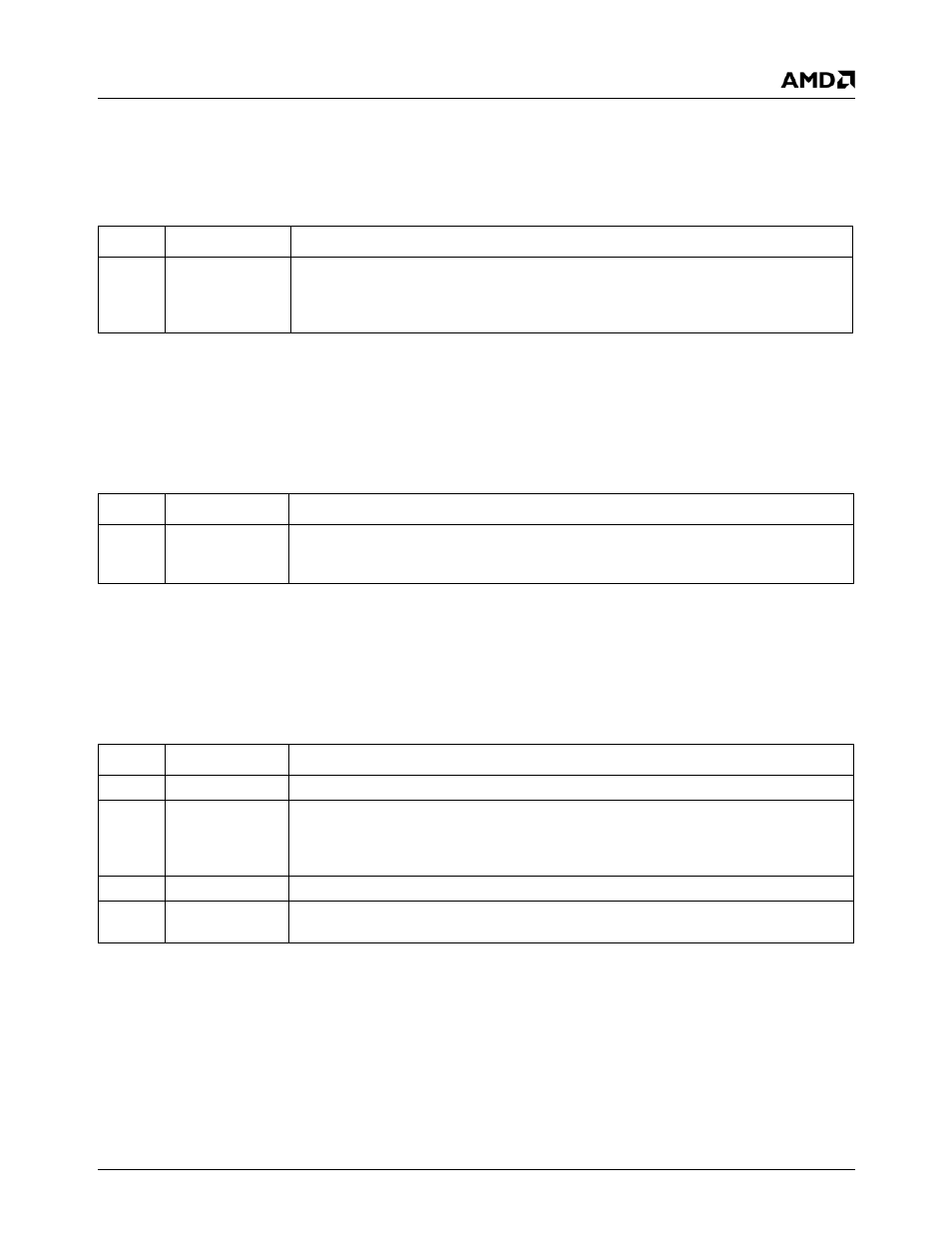
6.6.19.21 Vertical Display Enable End
6.6.19.22 Offset
6.6.19.23 Underline Location
Index
12h
Type
R/W
Reset Value
00h
Vertical Display Enable End Register Bit Descriptions
Bit
Name
Description
7:0
V_DISP_EN_
END
Vertical Display Enable End Register Bits [7:0]. This is a 10-bit value that specifies
the scan line where the vertical display enable signal goes inactive. It represents the
number of active scan lines minus 1. Bits 9 and 8 of this value are in the Overflow regis-
ter (Index 07h[6,1]).
Index
13h
Type
R/W
Reset Value
00h
Offset Register Bit Descriptions
Bits
Name
Description
7:0
OFST
Offset. This field specifies the logical line width of the screen. This value (multiplied by
two or four depending on the CRTC clocking mode) is added to the starting address of
the current scan line to get the starting address of the next scan line.
Index
14h
Type
R/W
Reset Value
00h
Underline Location Register Bit Descriptions
Bit
Name
Description
7
RSVD
Reserved.
6
DW
Doubleword Mode. When this bit is a 1, CRTC memory addresses are DWORD
addresses, and the CRTC refresh counter effectively increments by 4. When this bit is a
0, the address increment is determined by the Byte Mode bit in the CRTC Mode Control
register (Index 17h[6]).
5
RSVD
Not Implemented. (Count by 4)
4:0
UL
Underline Location. This field specifies the row scan value where the underline appears
in the character box in text modes.