27 interrupt control (gp_int_cntrl), Interrupt control (gp_int_cntrl), 0000ffffh – AMD Geode LX [email protected] User Manual
Page 277
AMD Geode™ LX Processors Data Book
277
Graphics Processor Register Definitions
33234H
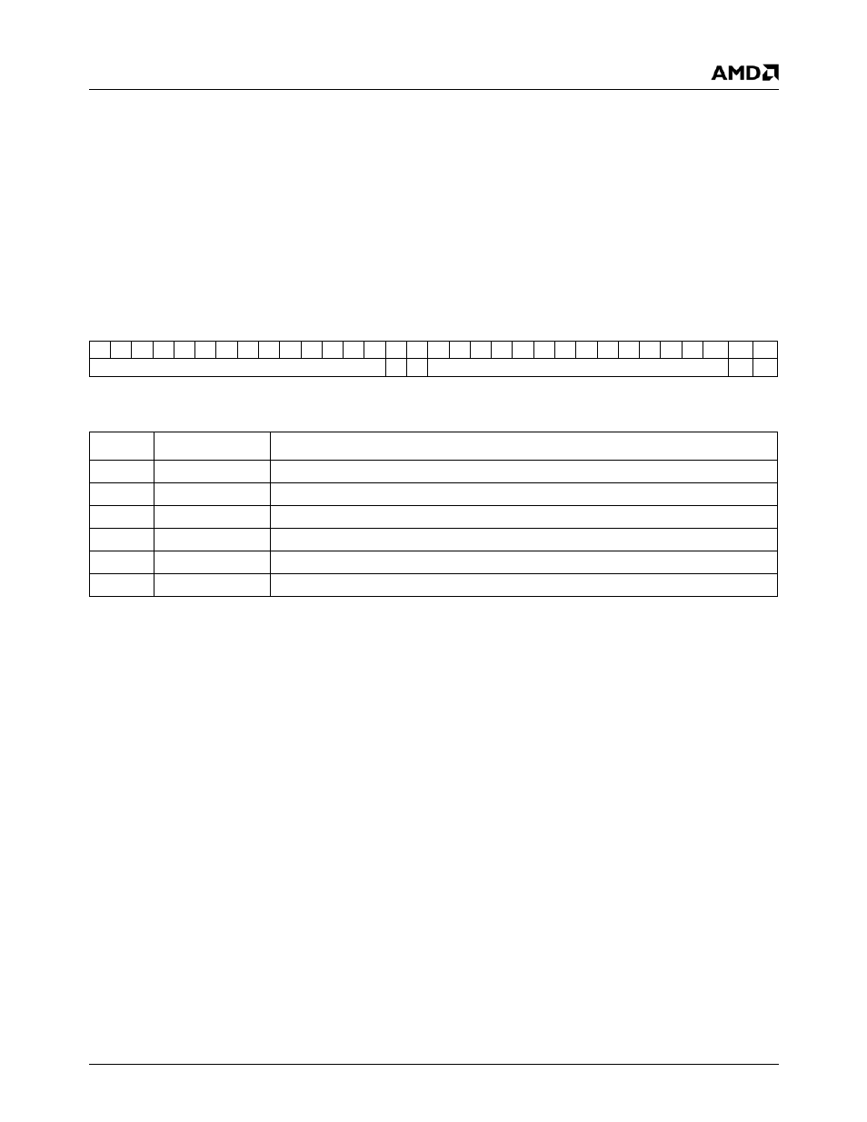
6.4.2.27 Interrupt Control (GP_INT_CNTRL)
This register is used to control the interrupt signal from the GP. It contains a 16-bit mask and a 16-bit interrupt detect. The
mask portion is read/write. A bit set in the mask register disables the corresponding interrupt bit. At reset, all interrupts are
disabled. The interrupt detect bits are automatically set by the hardware to indicate that the corresponding condition has
occurred and that the mask bit for that condition is not set. The interrupt detect bits remain set until they are cleared by a
write to the GP_INT_CNTRL register. Writing a 1 to an interrupt detect bit clears the bit. Writing a 0 to an interrupt detect bit
has no effect. Therefore, all of the interrupts in the GP may be cleared by reading the GP_INT_CNTRL register and writing
back the value that was read. Whenever any of the interrupt detect bits are set in this register, the IN bit will be set in the
GP_BLT_STATUS register (GP Memory Offset 44h[1]).
GP Memory Offset 78h
Type
R/W
Reset Value
0000FFFFh
GP_INT_CNTRL Register Map
31
30
29
28
27
26
25
24
23
22
21
20
19
18
17
16
15
14
13
12
11
10
9
8
7
6
5
4
3
2
1
0
RSVD
I1
I0
RSVD
M1 M0
GP_INT_CNTRL Bit Descriptions
Bit
Name
Description
31:18
RSVD
Reserved. Read returns 0.
17
I1
GP Idle Detect Interrupt.
16
I0
Command Buffer Empty Detect Interrupt.
15:2
RSVD
Reserved. Read returns 1.
1
M1
GP Idle Mask Bit.
0
M0
Command Buffer Empty Mask Bit.