4 signal descriptions, 1 system interface signals, Signal descriptions – AMD Geode LX [email protected] User Manual
Page 33
AMD Geode™ LX Processors Data Book
33
33234H
3.4
Signal Descriptions
3.4.1
System Interface Signals
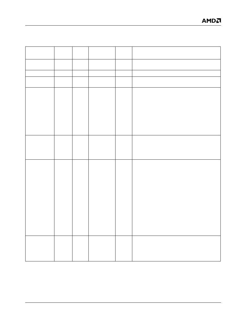
Signal Name
Ball
No.
Type
f
V
Description
SYSREF
Y31
I
33, 66 MHz
3.3
System Reference. PCI input clock; typically 33 or
66 MHz.
DOTREF
AB1
I
48 MHz
3.3
Dot Clock Reference. Input clock for DOTCLK PLL.
INTA#
AD28
I/O
(PD)
0-66 Mb/s
3.3
Interrupt. Interrupt from the AMD Geode LX proces-
sor to the CS5536 companion device (open drain).
IRQ13
AB29
(Strap)
I/O
(PD)
0-66 Mb/s
3.3
Interrupt Request Level 13. When a floating point
error occurs, the AMD Geode LX processor asserts
IRQ13. The floating point interrupt handler then per-
forms an OUT instruction to I/O address F0h or F1h.
The AMD Geode LX processor accepts either of
these cycles and clears IRQ13.
IRQ13 is an output during normal operation. It is an
input at reset and functions as a boot strap for tester
features on a board. It must be pulled low for normal
operation.
CIS
AE29
I/O
0-66 Mb/s
3.3
CPU Interface Serial. The GLCP I/O companion
interface uses the CIS signal to create a serial bus. It
contains INTR#, SUSP#, NMI#, INPUT_DIS#,
OUTPUT_DIS#, and SMI#. For details see
"GIO_PCI Serial Protocol" on page 538.
SUSPA#
AC31
(Strap)
I/O
0-66 Mb/s
3.3
Suspend Acknowledge. Suspend Acknowledge
indicates that the AMD Geode LX processor has
entered low-power Suspend mode as a result of
SUSP# assertion (as part of the packet asserted on
the CIS signal) or execution of a HLT instruction.
(The AMD Geode LX processor enters Suspend
mode following execution of a HLT instruction if the
SUSPONHLT bit, MSR 00001210h[0], is set.)
The SYSREF input may be stopped after SUSPA#
has been asserted to further reduce power con-
sumption if the system is configured for 3 Volt Sus-
pend mode.
SUSPA# is an output during normal operation. It is
an input at reset and functions as a boot strap for fre-
quency selection on a board. It must be pulled high
or low to invoke the strap.
PW0, PW1
AL18,
AJ17
(Strap)
I/O
0-300 Mb/s
3.3
PowerWise Controls. Used for debug.
PWx is an output during normal operation. It is an
input at reset and functions as a boot strap for fre-
quency selection on a board. It must be pulled high
or low to invoke the strap.