Table 3-7, Signal behavior during and after reset – AMD Geode LX [email protected] User Manual
Page 43
AMD Geode™ LX Processors Data Book
43
33234H
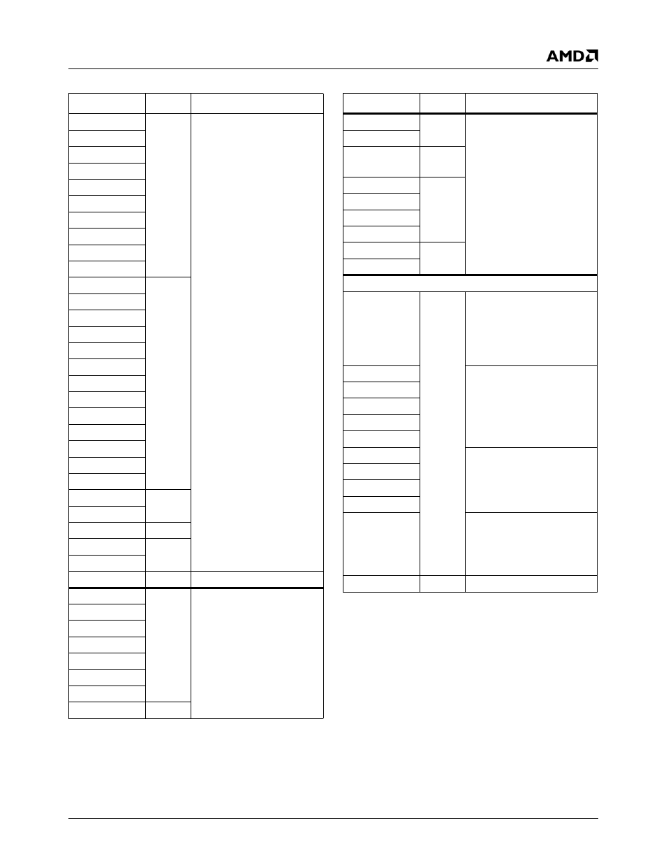
Table 3-7. Signal Behavior During and After Reset
Signal Name
Type
Behavior
AD[31:0]
PCI
TRI-STATE during RESET#
low
INTA#
PAR
REQ#
IRDY#
FRAME#
GNT#
DEVSEL#
TRDY#
STOP#
BA[1:0]
DDR
CAS[1:0]#
CBE[3:0]#
CS[3:0]#
DQ[63:0]
DQM[7:0]
DQS[7:0]
MA[13:0]
RAS[1:0]#
SDCLK[5:0]P
SDCLK[5:0]N
TLA[1:0]
WE[1:0]#
TDO
Debug
TDBGO
VIPSYNC (PD)
VIP
IRQ13
System
SUSPA#
DRGB[31:24]
Video
PD during reset.
VSYNC
Video
Driven low during RESET# low
HSYNC
DISPEN
DOTCLK
DRGB[23:0]
LDEMOD
VDDEN
CKE[1:0]#
DDR
VID[7:0] (PD)
Video
Inputs during RESET# low
VIPCLK
CIS
System
TDBGI
Debug
TMS
TDI
TCLK
SYREF
System
DOTREF
Power-up states after RESET#
DRGB[31:24]
Video
TRI-STATE with pin PD:
— Display filter can enable
outputs to drive alpha
(disables PDs).
— VIP can enable as inputs
(disables PDs).
DRGB[23:0]
Driven
DOTCLK
HSYNC
VSYNC
DISPEN
VDDEN
Input with PD
LDEMOD
VID[7:0]
VIPCLK
VIPSYNC
Input with PD:
— PD remains if pin is used
as input.
— PD disables if VIP drives
pin.
PW[1:0]
System
TRI-STATE
Signal Name
Type
Behavior