Bcm400 expansion gateway – Nortel Networks BCM200/400 User Manual
Page 65
Chapter 2 Introducing the BCM hardware
65
BCM200/400 4.0 Installation and Maintenance Guide
•
provides the functionality of a DTM (T1 digital lines only)
•
splits the incoming T1 line so that some of the lines are used for voice traffic and some of the
lines are used for data traffic
•
provides either the channel service unit (CSU) or data service unit (DSU) functionality to
support connections to data terminal equipment (DTE), such as a router or a bridge
•
connects to network devices that support V.35 interfaces
•
provides end-to-end transparent bit service
•
supports loopbacks between the BCM system and the internal BCM components, and between
the BCM system and digital terminal equipment
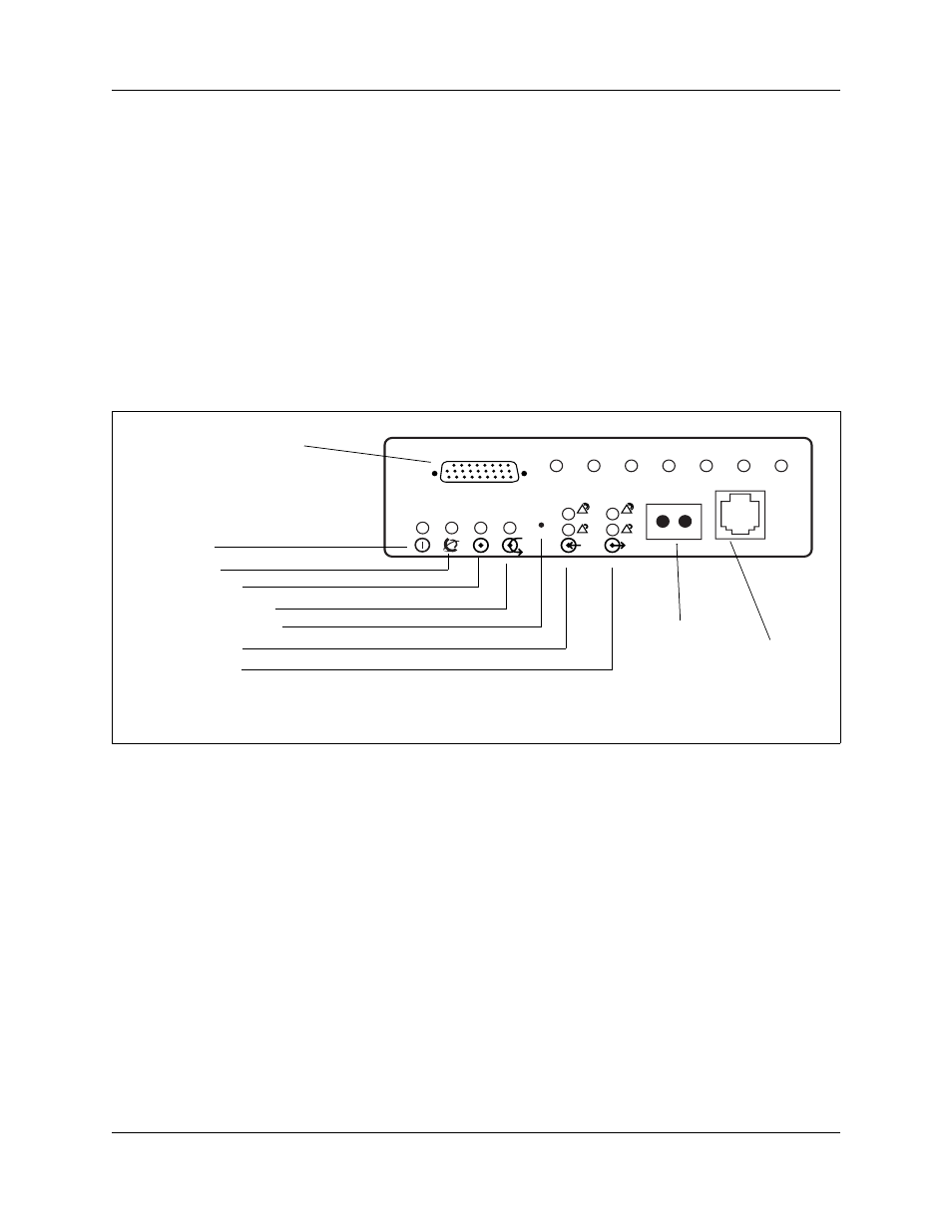
shows the DDIM faceplate LEDs and connectors.
Figure 36 DDIM faceplate LEDs and connectors
BCM400 expansion gateway
The BCM400 expansion gateway is available in standard and redundant configurations for
BCM400 systems only.
The BCM400 expansion gateway kit (North America only) consists of a BCM400 main unit and
enough VoIP gateway trunk authorization codes to enable 48 ports of VoIP trunks. The BCM400
expansion gateway, combined with the BCM400 host system, provides a maximum of 192 TDM
sets, instead of 160, while communicating to the PSTN through TDM trunks on the expansion
gateway. The VoIP trunks connect the two systems and allow the BCM400 expansion gateway to
tandem from IP trunks to the PSTN/TDM trunks (see
The addition of a second BCM400 expansion gateway provides up to two T1 PSTN trunks. This
releases enough system resources on the host BCM400 main unit for the addition of 64 digital
telephones.
RxD
TxD
RTS
CTS
DCD
DSR
TM
10101
Data module serial port
Power LED
Status LED
In Service LED
Loopback test LED
Continuity loopback
Receive LEDs
Transmit LEDs
Loopback
RJ-48C digital telephone line
connector