Determining bus requirements – Nortel Networks BCM200/400 User Manual
Page 113
Chapter 8 Installing a media bay module (MBM)
113
BCM200/400 4.0 Installation and Maintenance Guide
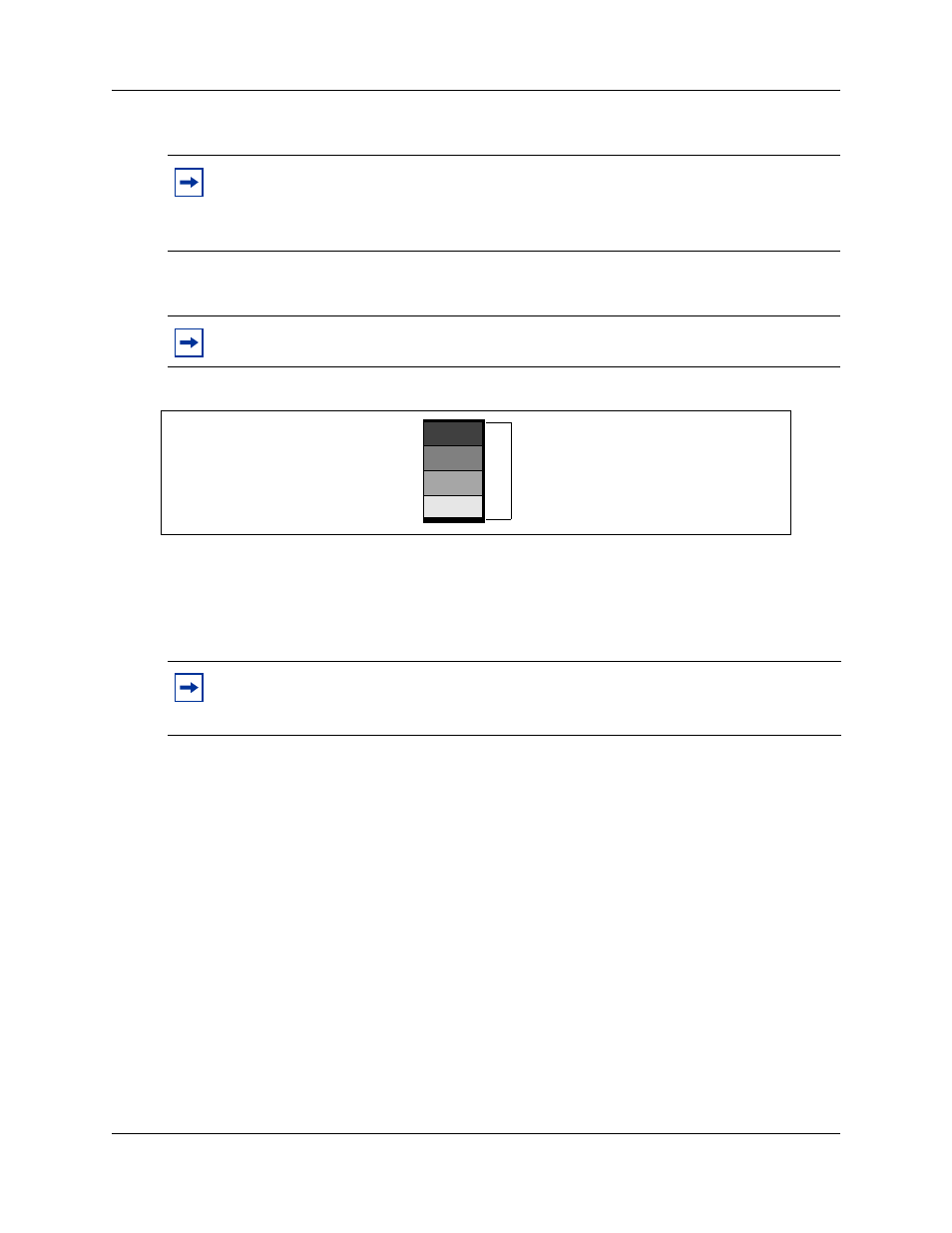
Offsets are assigned using DIP switches 1, 2, and 3 on the MBM.
shows a DS30 broken down into four offset groups of four (single density)
or eight (double density) lines each.
Figure 66 Offsets are part of DS30 channel line groups
Determining bus requirements
shows the DS30 bus requirements of each MBM. Note the differences between MBMs
set to single density and MBMs set to double density.
Note: MBMs that do not, or cannot, share DS30 buses always assign the offset as 0
(zero). As well, if the MBM requires more than one bus, such as the 4x16, 8x16, or the
DDIM, only the first DS30 is set on the DIP switches. The next consecutive DS30 bus is
automatically assigned by the MBM.
Note: When you enable a station MBM for double density, the line numbers double.
Note: If you choose a CTM8, DDIM, 4x16, or 8x16 there are some restrictions on the
offsets you can choose. Refer to the DIP switch settings in
and
“4x16 switch settings” on page 130
for details.
Offset 0
Offset 1
Offset 2
Offset 3
Offsets have
4 lines (single-density)
8 lines (double-density)
1 DS30 bus
16 lines/32 time slots (single-density)
32 lines/32 time slots (double-density)