Figure 154 – Nortel Networks BCM200/400 User Manual
Page 300
300
Chapter 23 Replacing or upgrading a power supply
N0060612
N0060612
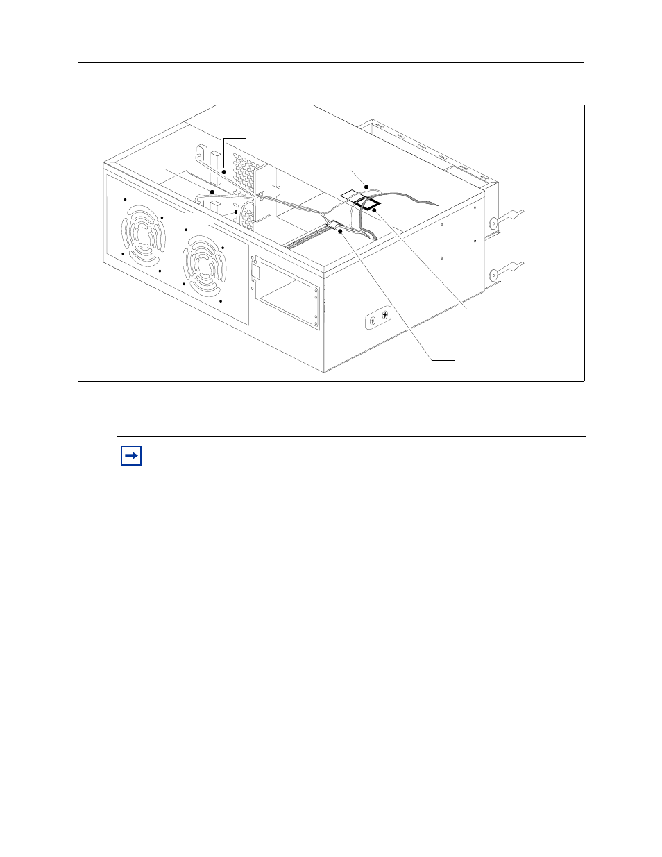
Figure 154 Install a new cable clamp
18 Run the power supply, auxiliary, and IDE cables to the hard disk. Secure these cables in the
new cable clamp.
19 Connect cable runs P2 and P3 to the media bay backplane (see
) as follows:
a
Bundle the cables together. Run the cables on the top of the power supply chassis and
secure with the cable clamp.
b
Connect cable P2 into the bottom media bay module backplane power connector.
c
Connect cable P3 into the top media bay module backplane connector.
d
Bundle power cables P2 and P3 along with auxiliary cable (P7 or P8) together with a
grommet (see
).
e
Insert the P2, P3, and auxiliary cable into the cable slot on the chassis (secured with the
grommet).
f
Ensure that one power run connects to one MBM backplane connector. Do not connect a
single power run to both MBM backplane connectors.
Note: Verify the power supply cables are connected correctly and are routed so they do
not interfere with any internal components when moved.
Mount new cable
clamp - located
on underside of
cover
P2
P3
Auxiliary
Auxiliary
Cable clamp - located
on top of power supply