Base function tray internal components, Table 5 – Nortel Networks BCM200/400 User Manual
Page 42
42
Chapter 2 Introducing the BCM hardware
N0060612
N0060612
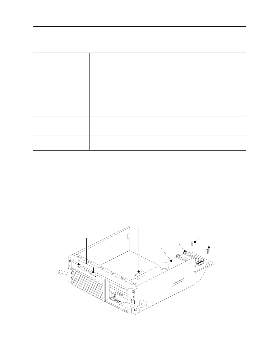
Base function tray internal components
The base function tray installs in the main unit and houses the main card with the system
interfaces.
illustrates the base function tray layout (BCM200 configuration shown).
describes the internal components.
Figure 9 Base function tray internal components
Table 5 Base function tray faceplate component descriptions
Component
Description
System Status LEDs
The system status display LEDs indicate the current status of the hardware
components (see
“Base function tray system status display LEDs” on page 79
Reset button
The reset button restarts the BCM system.
WAN card
The WAN card (field upgrade) connects the BCM system to the wide area network
(WAN). See
“WAN interface card” on page 48
.
Media services card (MSC)
The MSC performs call processing and media processing of the voice channels for
the BCM system. See
“Media services card (MSC)” on page 43
USB (universal serial bus)
port
The two USB ports connect USB-compatible peripherals to the BCM system.
Modem port
The modem port provides PSTN dial-up access to the BCM system.
COM port (or serial port)
The COM port provides a serial connection to a laptop for maintenance purposes.
See
“Connecting through the serial port” on page 187
Ethernet port 2
Ethernet port 2 provides access to the internal local area network.
Ethernet port 1
Ethernet port 1 provides access to the external local area network.
MSC
System Status LEDs
MSC mounting
screws
PEC III
slots
DS256 interface