Dsmc2 helium operation guide, Sync trigger button circuit, Compatible cables – RED DIGITAL CINEMA DSMC2 BRAIN with HELIUM 8K S35 Sensor (2018 Unified DSMC2 Lineup) User Manual
Page 230

SYNC TRIGGER BUTTON CIRCUIT
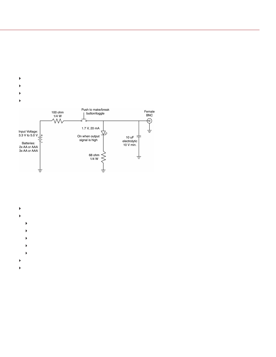
The SYNC connector has a 3.3 V Schmitt trigger (5 V tolerant). The trigger is not a switch closure circuit, so it requires
that the trigger source supplies current. Both edges of the input signal may be used as a trigger.
NOTE:
The SYNC trigger button circuit only applies to the DSMC2 Base Expander.
For example, this is the behavior of the circuit when the GPI trigger is used for record start/stop:
Start Record
: On ground to 3.3 V transition
During Record
: Hold at 3.3 V
Stop Record
: On 3.3 V to ground transition
During Stop
: Hold at ground
Figure: Trigger Button Circuit Diagram
NOTE:
In the diagram above, values are approximate. Use standard values.
COMPATIBLE CABLES
790-0154, 790-0643
: 3BNC-to-00 Sync Cable
790-0187, 790-0648
: 4-Pin 00B-to-Flying Lead
White
: Ground
Yellow
: RS232 RX
Blue
: Shutter/sync, general purpose output
Red
: RS232 TX
Black
: Shield
790-0415
: RED Start/Stop Cable (14-Pin 1B to SYNC, CTRL, BNC)
790-0428
: RED Start/Stop Cable (14-Pin to 00B SYNC)
C O PYR I G HT © 2 0 1 9 R ED.C O M , LLC
9 5 5 - 0 1 6 8 _V 7 .1 , R EV - M
|
2 3 0
DSMC2 HELIUM OPERATION GUIDE
