Yaskawa DR2 Sigma Servo User Manual
Page 61
2.4 Conducting a Test Run
47
2.4.5 Minimum User Constants Required and Input Signals
1) This section describes the minimum user constants that must be set to conduct a test run.
For details on how to set each user constant, refer to 4.1.5 Operation in User Constant
Setting Mode.
a) Servopack in speed/torque control mode
Cn-03
Speed reference gain
Cn-0A
Dividing ratio setting
b) Servopack in torque control mode
Cn-13
Torque reference adjustment gain
Cn-0A
Dividing ratio setting
c) Servopack in position control mode
Cn-02 bits 3, 4 and 5
Reference pulse form selection
Cn-24
Electronic gear ratio (numerator)
Cn-25
Electronic gear ratio (denominator)
After changing the Cn-02 setting, always turn the power OFF, then ON. This makes
the new setting valid.
2) If the specified direction of rotation differs from the actual direction of rotation, the wiring
may be incorrect. In this case, recheck the wiring and correct it accordingly. Then, if the
direction of rotation is to be reversed, set the following user constant:
Cn-02 (bit 0)
Reverse rotation mode
After changing the Cn-02 setting, always turn the power OFF, then ON. This makes the
new setting valid.
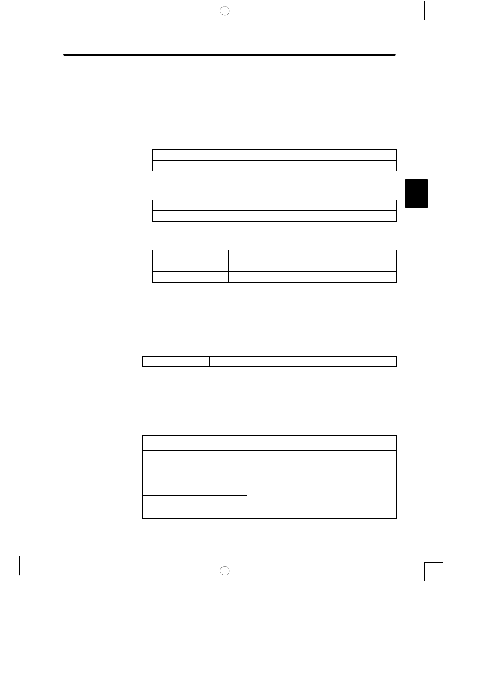
3) The following table lists the minimum input signals required to conduct a test run. For de-
tails of each input signal, refer to the relevant page.
Signal Name
Pin
Number
Function
S-ON
(servo ON)
1CN-40
Switching between motor ON and OFF status.The
memory switch can be used to eliminate the need for
external short-circuit wiring (see page 132).
P-OT
(forward
rotation
prohibited)
1CN-42
Overtravel limit switch
The memory switch can be used to eliminate the
N-OT
(revere
rotation
prohibited)
1CN-43
The memory switch can be used to eliminate the
need for external short-circuit wiring (see page 54).
2