Yaskawa DR2 Sigma Servo User Manual
Page 193
USING THE DIGITAL OPERATOR
4.1.6 Operation in Monitor Mode cont.
180
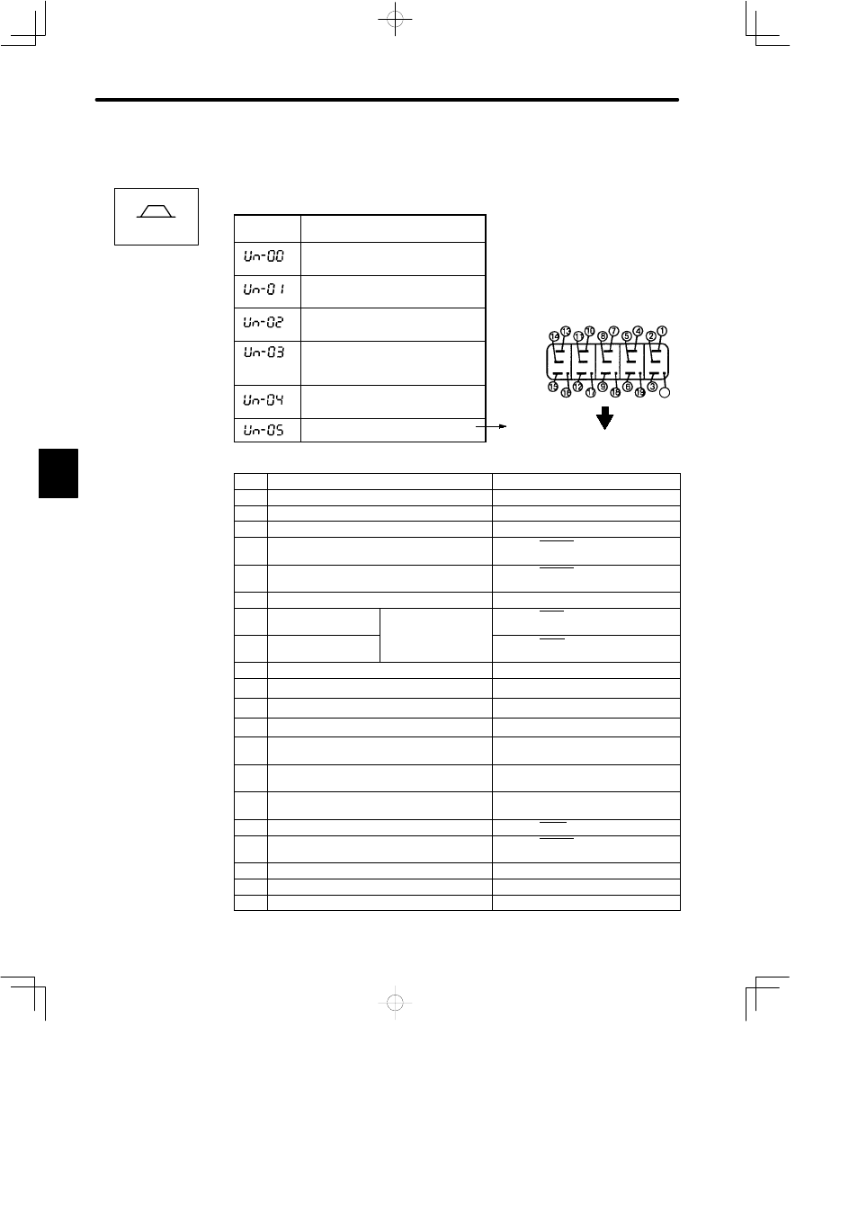
3) Keys to Monitor Mode Display are shown below. Note that the display differs between the
speed/torque control and position control types.
For Speed/Torque Control
Monitor
Number
Monitor Display
Actual motor speed
Units: r/min
Input speed reference
Units: r/min
Internal torque reference
Units: %
(with respect to rated torque)
Number of pulses from motor
U-phase edge
Units: pulses
Electrical angle
Units: 0.1deg
Internal status bit display
Bit #
Description
Related I/O Signal, User Constant
1
Servo alarm
1CN-31(ALM)
2
Dynamic brake ON
3
Reverse rotation mode
Cn-02 Bit 0, 2CN-7(DIR)
4
During motor rotation or brake interlock signal 1CN-27 (TG-ON), status display
mode
5
Torque limit or speed coincide
1CN-25 (V-CMP), status display
mode
6
Mode switch ON
7
During forward torque
limit
Or contact input
speed control
1CN-45 (P-CL)
8
During reverse torque
limit
speed co o
1CN-46 (N-CL)
9
Motor power ON
10
A-phase
2CN-33(PA), 2CN-34(
£
PA)
11
B-phase
2CN-35(PB), 2CN-36(
£
PB)
12
C-phase
2CN-19(PC), 2CN-20(
£
PC)
13
U-phase
Only when incremental encoder is
used.
14
V-phase
Only when incremental encoder is
used.
15
W-phase
Only when incremental encoder is
used.
16
Servo ON
1CN-40 (S-ON) , Cn-01 Bit 0
17
P operation, zero clamp, or rotation direction
input
1CN-41 (P-CON) , Cn-01 Bit A, B,
Cn-02 Bit 2
18
Forward overtravel
1CN-42 (P-OT), Cn-01 Bit 2
19
Reverse overtravel
1CN-43 (N-OT), Cn-01 Bit 3
20
SEN signal input
1CN-4 (SEN)
4
Speed/Torque
Internal Status
Bit Display
see below
20