Yaskawa DR2 Sigma Servo User Manual
Page 54
BASIC USES OF Σ-SERIES PRODUCTS
2.4.2 Step 1: Conducting a Test Run for Motor without Load cont.
40
(4) Turn the power ON.
Turn the Servopack power ON. If the Servo-
pack is turned ON normally, the LED on the
Digital Operator lights up as shown in the fig-
ure.
Power is not supplied to the servomotor be-
cause the servo is OFF.
If an alarm display appears on the LED as
shown in the figure above, the power supply
circuit, motor wiring or encoder wiring is incor-
rect. In this case, turn the power OFF, then cor-
rect the problem.
(5) Operate using the Digital Operator
Operate the motor with the Digital Operator.
Check that the motor runs normally.
Refer to 4.2.2 Operating Using the Digital Op-
erator.
(6) Connect signal lines.
Connect connector 1CN as follows:
(1) Turn the power OFF.
(2) Return the alarm signal circuit shorted in the
above step (3) to its original state.
(3) Connect connector 1CN.
(4) Turn the power ON again.
(7) Check input signals.
Check the input signal wiring in monitor mode.
For the checking method, refer to 4.1.6 Opera-
tion in Monitor Mode.
• Checking method
Turn each connected signal line ON and
OFF to check that the monitor bit display
changes accordingly.
Input Signal
ON/OFF
Monitor Bit Display
High level or open
OFF
Extinguished
0 V level
ON
Lit
2
Operation by Digital Operator
If an alarm occurs, the power supply
circuit, motor wiring, or encoder
wiring is incorrect.
After turning the power OFF, re-
move the short circuit.
Connect
connector
1CN.
ALM+
ALM-
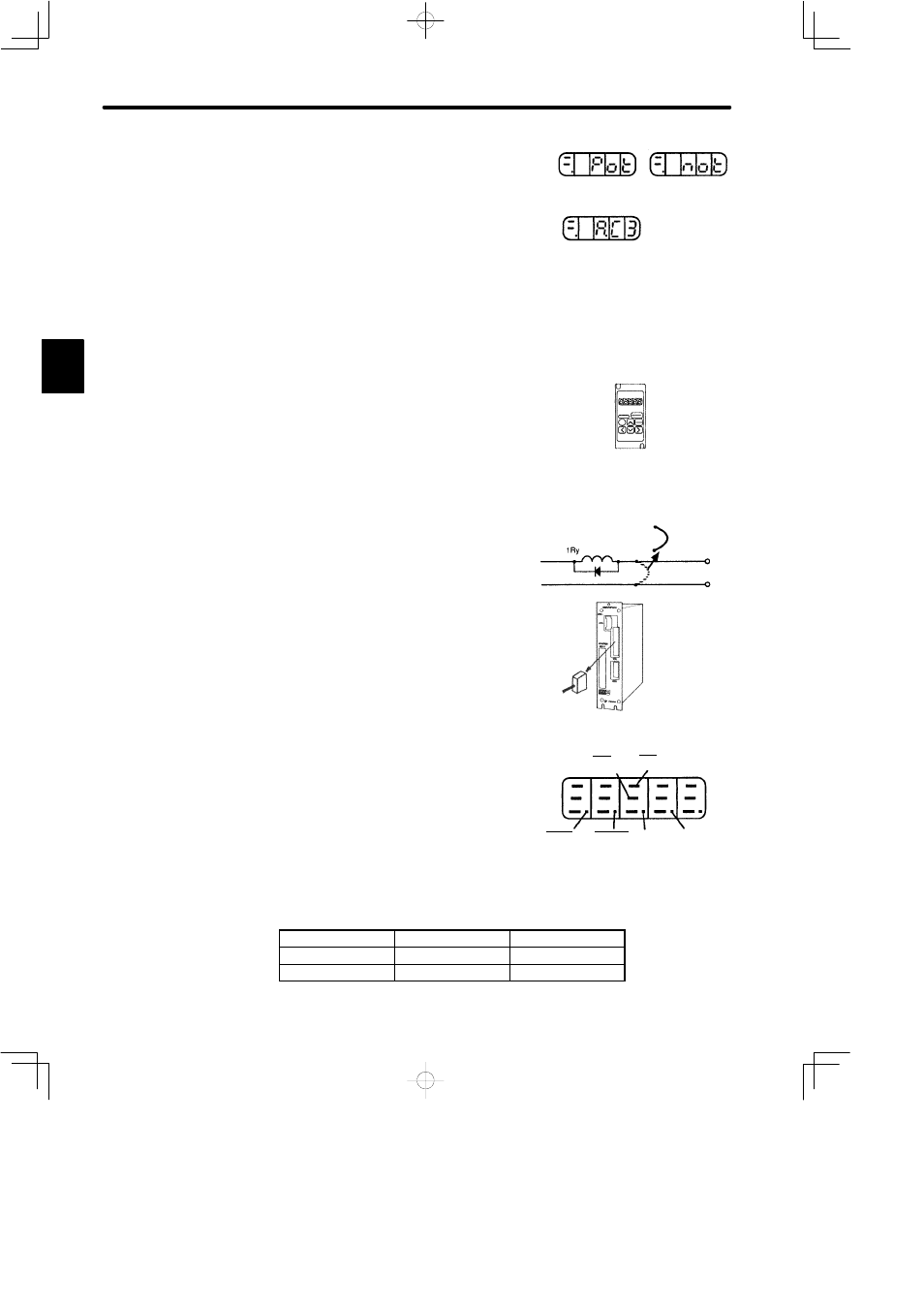
Internal status bit display
(Un-05, Un-06)
Example of
Un-05
The memory switch can be
used to
eliminate the need
for
external short-circuits in
wiring (Refer to 3.1.2).
S-ON
(1CN-40)
P-CON
(1CN-41)
P-OT
(1CN-42)
N-OT
(1CN-43)
N-CL
(1CN-46)
P-CL
(1CN-45)