Yaskawa DR2 Sigma Servo User Manual
Page 167
APPLICATIONS OF Σ-SERIES PRODUCTS
3.8.5 Using an Absolute Encoder cont.
154
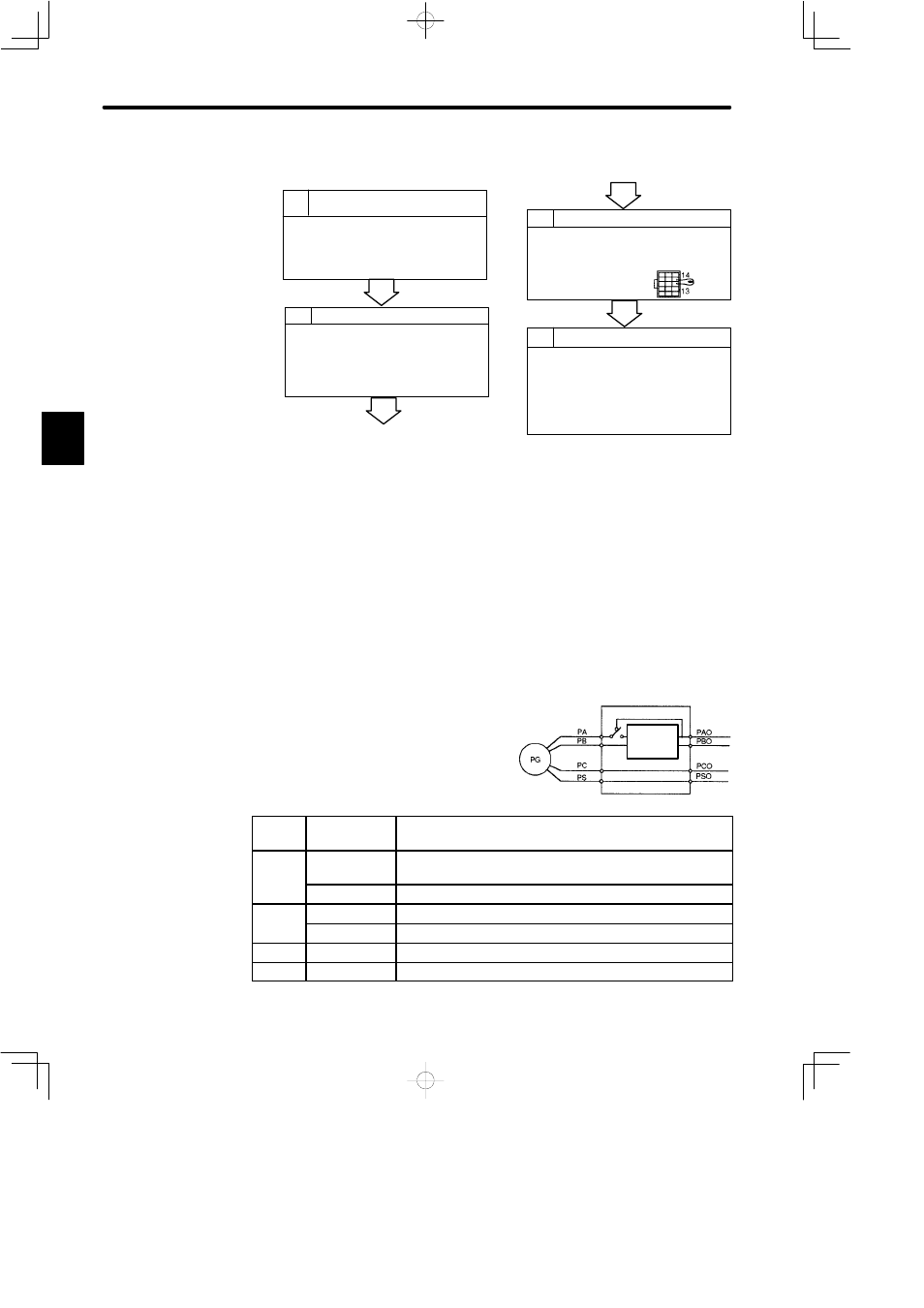
b) The setup procedure is as follows:
1
Turning DR2 Servopack Control
Power ON
• Wire the DR2 Servopack, motor and encoder in the
normal way.
• Connect the battery and turn the DR2 Servopack
ON.
2
3
Resetting Data
• Turn the DR2 Servopack control power OFF, then
disconnect the encoder connector.
• Short-circuit encoder connector terminals 13 and
14 for two seconds or more.
4
Turning the Encoder ON
• Set the SEN signal at high level.
• Keep the encoder turned ON for at least three min-
utes.
• It does not matter even if alarm status arises.
Turning the Power ON
• Return the wiring to the original state.
• Turn the DR2 Servopack control power ON and set
the SEN signal at high level.
• If alarm “A.00” arises, repeat the same procedure
from the beginning.
• If no problem has occurred, the setup procedure is
complete.
NOTE
Setting up the encoder sets the revolution count inside the encoder to 0.
After setting up the encoder, always reset the machine home position. Operating the ma-
chine without the home position being reset does not only damage the machine but may
also cause an accident resulting in injury or death.
7) Absolute Data Exchange Sequence
The Servopack sends absolute data to the host controller when receiving output from a
12-bit absolute encoder. This data exchange sequence is described below.
Use the following detailed information when designing a host controller.
a) Outline of Absolute Signal
The 12-bit absolute encoder outputs PAO,
PBO, PCO and PSO as shown on the
right.
Signal
Name
Status
Contents
PAO
Initial state
Serial data
Initial incremental pulse
PAO
Normal state
Incremental pulse
PBO
Initial state
Initial incremental pulse
PBO
Normal state
Incremental pulse
PCO
Normal state
Home position pulse
PSO
Normal state
Rotation count serial data
3
Servopack
Frequency
dividing
circuit