Yaskawa DR2 Sigma Servo User Manual
Page 169
APPLICATIONS OF Σ-SERIES PRODUCTS
3.8.5 Using an Absolute Encoder cont.
156
d) Detailed Specifications of Each Signal
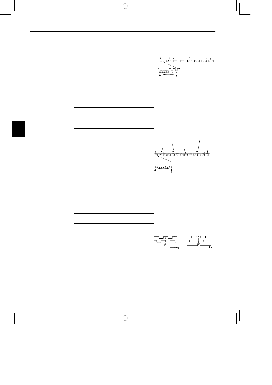
• Specifications of PAO Serial Data:
The number of revolutions is output in five dig-
its.
Data transmission
method
Start-stop synchronization
(ASYNC)
Baud rate
9600
Start bit
1 bit
Stop bit
1 bit
Parity
Even number
Character code
ASCII 7-bit code
Data format
8 characters. As shown on
the right.
• Specifications of PSO Serial Data:
The number of revolutions and the abso-
lute position within one revolution are al-
ways output in five and four digits, respec-
tively.
The
transmission
cycle
is
approximately 40 ms.
Data transmission
method
Start-stop synchronization
(ASYNC)
Baud rate
9600
Start bit
1 bit
Stop bit
1 bit
Parity
Even number
Character code
ASCII 7-bit code
Data format
13 characters. As shown on
the right.
• Incremental Pulse and Home Position
Pulse:
Initial incremental pulses which pro-
vide absolute data are first divided by
the frequency divider inside the Servo-
pack and then output in the same way
as normal incremental pulses.
3
“P” or “A”
“+” or “-”
Data
Start bit
Even parity
• Data is P+00000 (CR) or P−00000
(CR) when the number of revolu-
tions is zero.
• The maximum number of revolu-
tions is 99999. If this value is ex-
ceeded, it returns to 00000.
”0” to “9””
“CR”
“P” or “A”
“+” or “-”
Number of
revolutions: “0” to “9”
“+” or “-”
Absolute position
within one revolution:
“0” to “9”
Data
Start bit
Even parity
• Absolute position data within one revolu-
tion is a value before frequency dividing.
(4,096 pulses per revolution)
• Absolute position data increases during
forward rotation (standard setting).
(Not valid in reverse rotation mode)
“CR”
Phase A
Phase B
Phase C
Forward
rotation
Reverse
rotation
• Note that phase C is not divided so its pulse
width is narrower than phase A.
Phase A
Phase B
Phase C