Yaskawa DR2 Sigma Servo User Manual
Page 329
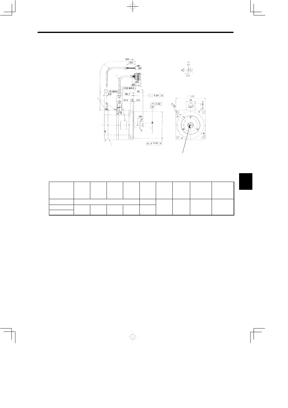
5.4 Σ-Series Dimensional Drawings
317
• 750 W (1.01HP)
Holding Brake
(Deenergisation Operation)
Voltage depends on the last
symbol of motor type:
B: 90VDC C: 24VDC
Brake Holding Torque = Motor
Rated Torque
(1.10)
Incremental
Encoder
2048 P/R
Cross-section Y-Y
4-φ10
(φ 0.39)
MTG Holes
Motor Lead
UL2464 φ7 (φ0.29)
Sealant
(0.0016)
(0.0008)
(6.22 MAX)
(11.81¦1.18)
(1.38)
(0.14)
(11.81¦1.18)
11
0
0 -0.035
4.33
-0.0014
0
φ
(
)
(4.72)
(0.38)
Marked Wire
Name
plate
φ
16
0 -0.01
1
0.63
-0.0004
0
φ
(
)
(φ 0.0016)
Encoder Lead
UL2854φ 6
(φ 0.24)
(1.38)
(1.57)
(1.50)
(0.41)
Screw
Hex. Nut
17 (0.67)
(φ 5.71)
(2.63)
(0.75)
(4.65 MAX)
φ
Shaft end screw hole
(SGMP-08V316B(C),
with key type only)
Type SGMP-
QK
U
W
T
Screw
dimens
ions
Output
W
(HP)
Approx.
mass
kg
(lb)
Allowable
radial load
N (lb)
Allowable
thrust load
N (lb)
08V312B(C)
No key
−
750
(1 01)
5.7
(12 57)
392 (88.1)
147 (33.0)
08V314B(C)
22(0.87) 3(0.12)
5(0.20)
5(0.20)
M5
D
h
(1.01)
(12.57)
(
)
(
)
08V316B(C)
(
)
(
)
(
)
(
)
Depth 8
Note
1) The detector uses an incremental encoder 2048 P/R.
2) Type “V” indicates 200 V specification.
3) “08V314B(C)” and “08V316B(C)” have a keyed shaft. The keyway complies with JIS B
1301-1976 (precision). A straight key is supplied.
4) The quoted allowable radial load is the value at a position 35 mm (1.38 in.) from the mo-
tor mounting surface.
5) The electromagnetic brake is only to hold the load in position and cannot be used to stop
the motor.
6) Conforms to IP55 protective structure (except connector and output shaft faces).
5