Yaskawa DR2 Sigma Servo User Manual
Page 481
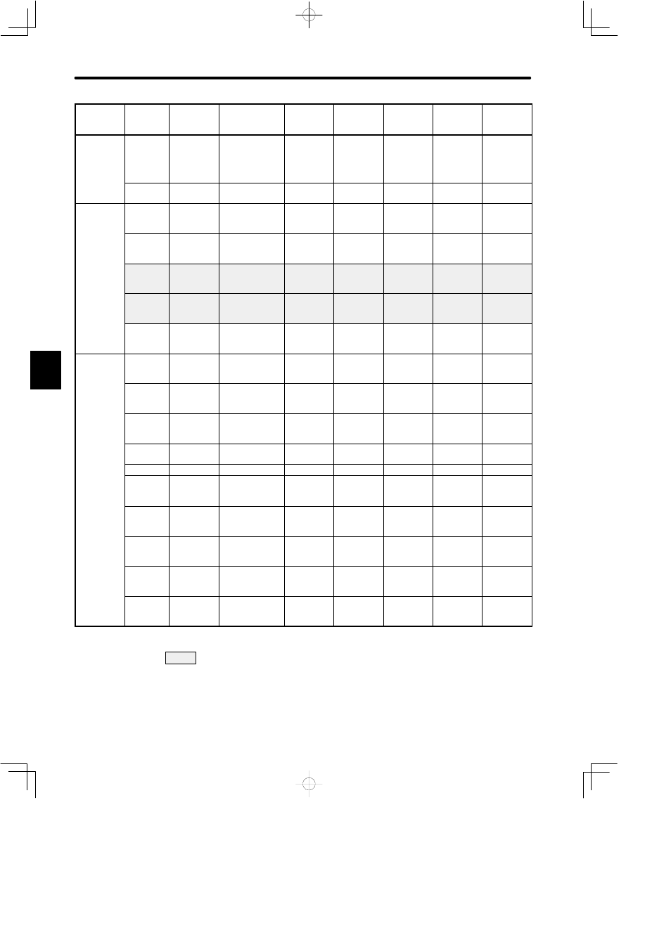
LIST OF USER CONSTANTS
472
Category
Remarks
Factory
Setting
Upper
Limit
Lower
Limit
Unit
Name
Code
User
Constant
No.
Sequence
Related
Constants
Cn-16
BRKWAI
Output timing
of brake
reference
during motor
operation
10 ms
10
100
50
See 3.4.4.
Cn-1B
COINLV
Positioning
complete range
Reference
unit
0
250
7
See 3.7.3.
Pulse
Related
Constants
Cn-0A
PGRAT
Dividing ratio
setting
P/R
16
32768
2048
See note 1
See 3.2.3.
Cn-11
PULSNO
Number of
encoder pulses
P/R
513
32768
2048
See note 1
See 3.3.3,
3.8.5.
Cn-24
RATB
Electronic gear
ratio
(numerator)
4
65535
4
See note 3
See 3.2.3,
3.2.5.
Cn-25
RATA
Electronic gear
ratio
(denominator)
1
65535
1
See note 3
See 3.2.3,
3.2.5.
Cn-2A
PULSNO2
External PG
number of
pulses
P/R
513
32768
2048
Other
Constants
Cn-0C
TRQMSW
Mode switch
(torque
reference)
%
0
Max.
torque
200
See 3.6.6.
Cn-0D
REFMSW
Mode switch
(speed
reference)
r/min
0
4500
0
See 3.6.6.
Cn-0E
ACCMSW
Mode switch
(acceleration
reference)
10 (r/min)/s 0
3000
0
See 3.6.6.
Cn-0F
ERPMSW
Mode switch
(error pulse)
Reference
unit
0
10000
0
See 3.6.6.
Cn-10
JOGSPD
Jog speed
r/min
0
4500
500
See 3.3.2.
Cn-1E
OVERLV
Overflow
×256
reference
unit
1
32767
1024
See note 4
See 3.5.2,
3.6.2.
Cn-1F
SPEED1
1st speed
(contact input
speed control)
r/min
0
4500
100
See 3.2.6.
Cn-20
SPEED2
2nd speed
(contact input
speed control)
r/min
0
4500
200
See 3.2.6.
Cn-21
SPEED3
3rd speed
(contact input
speed control)
r/min
0
4500
300
See 3.2.6.
Cn-28
NFBCC
Speed loop
compensation
constant
---
0
100
0
: User constants that must be always set
D