Configuration procedure – H3C Technologies H3C S10500 Series Switches User Manual
Page 39
28
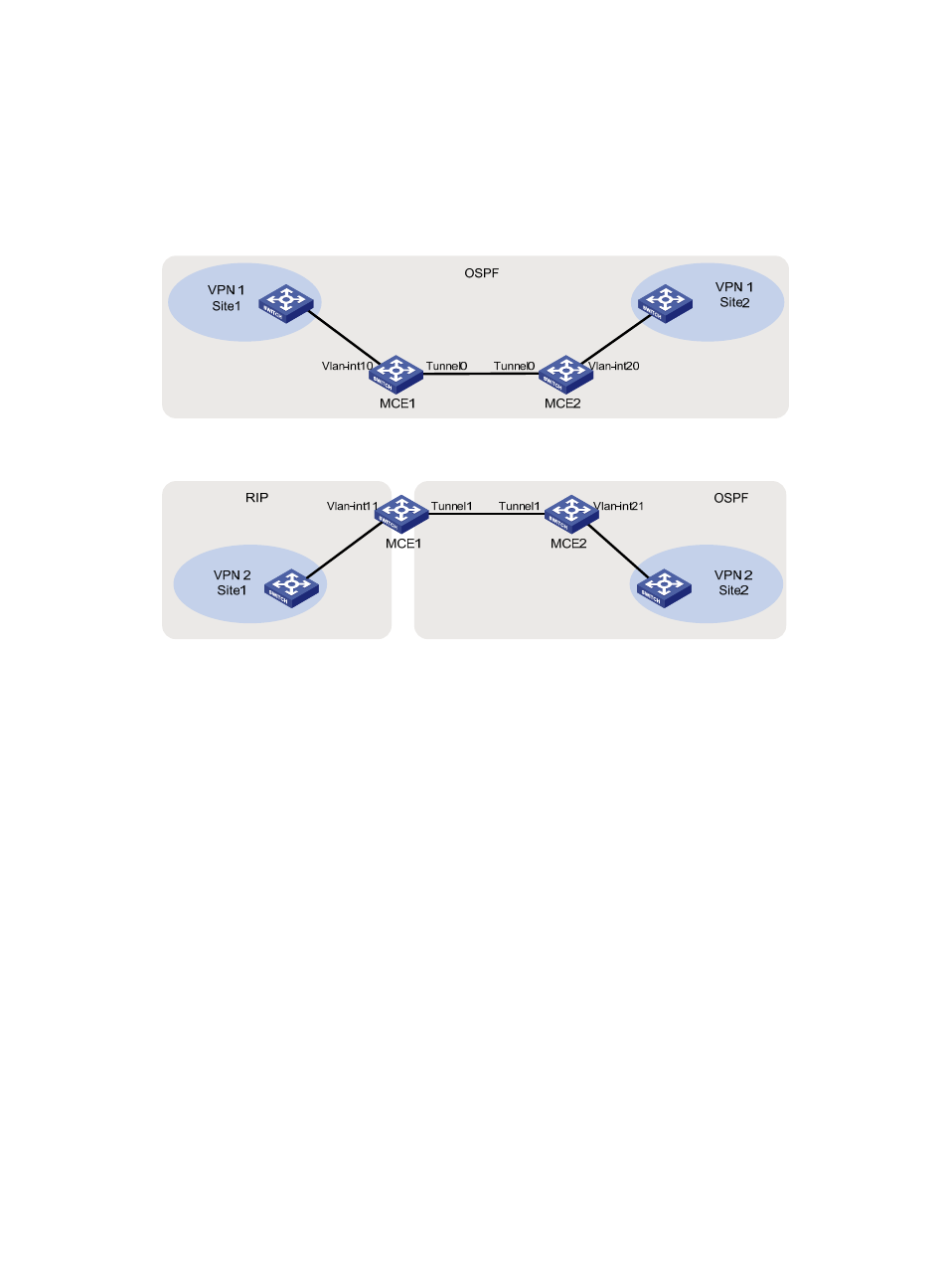
network is simplified into two separate topologies, as shown in
and
. Thus, MCEs
advertise routes of different VPNs through different paths.
For VPN 1, advertise interface addresses on the two MCEs in area 0, making the entire VPN a single
OSPF domain. For VPN 2, advertise interface addresses for RIP and OSPF calculations, and in addition,
redistribute OSPF routes to RIP and RIP routes to OSPF on MCE 1.
Figure 9 Network topology of VPN 1 with the MCEs
Figure 10 Network topology of VPN 2 with the MCEs
Configuration procedure
1.
Configure MCE 1.
# Create VLAN 100 and VLAN 101, configure GigabitEthernet 1/0/15 as a trunk port, and add it to the
two VLANs.
[MCE1] vlan 100 to 101
[MCE1] interface GigabitEthernet 1/0/15
[MCE1-GigabitEthernet1/0/15] port link-type trunk
[MCE1-GigabitEthernet1/0/15] port trunk permit vlan 100 101
[MCE1-GigabitEthernet1/0/15] quit
# Create VLAN interfaces, and configure IP addresses for them.
[MCE1] interface vlan-interface 100
[MCE1-Vlan-interface100] ip address 192.168.1.1 255.255.255.0
[MCE1-Vlan-interface100] quit
[MCE1] interface vlan-interface 101
[MCE1-Vlan-interface101] ip address 192.168.2.1 255.255.255.0
[MCE1-Vlan-interface101] quit
# Create the interface Tunnel0.
[MCE1] interface tunnel 0
# Configure an IP address for the Tunnel0 interface.
[MCE1-Tunnel0] ip address 10.1.1.1 255.255.255.0