Mpls l3vpn configuration examples, Network requirements, Configuration procedure – H3C Technologies H3C S10500 Series Switches User Manual
Page 278
267
NOTE:
For commands to display information about a routing table, see
Layer 3—IP Routing Command
Reference.
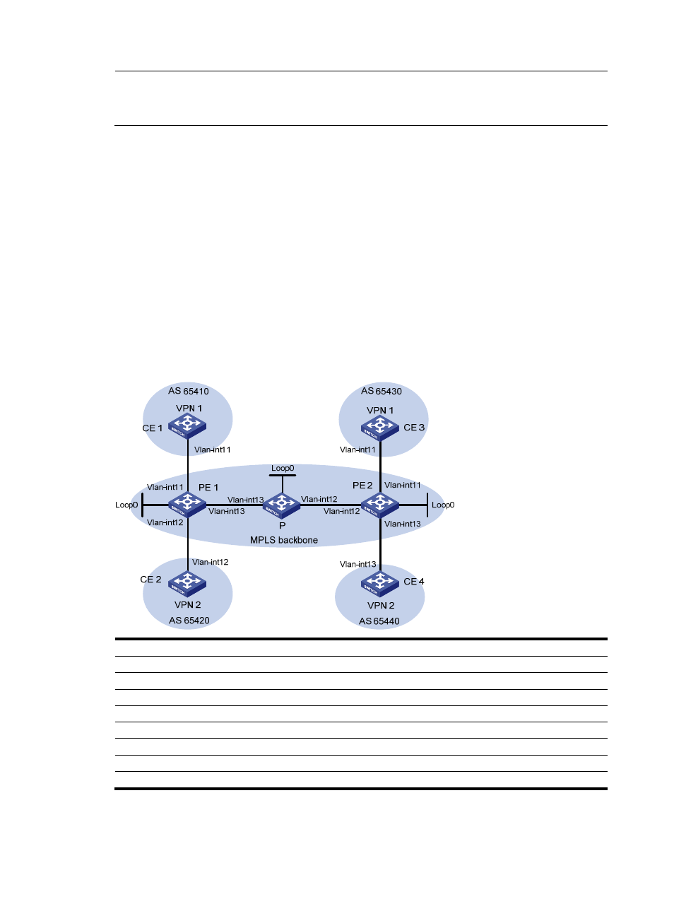
MPLS L3VPN configuration examples
Configuring MPLS L3VPNs using eBGP between PE and CE
Network requirements
•
CE 1 and CE 3 belong to VPN 1. CE 2 and CE 4 belong to VPN 2.
•
VPN 1 uses VPN target attribute 111:1. VPN 2 uses VPN target attribute 222:2. Users of different
VPNs cannot access each other.
•
eBGP is used to exchange VPN routing information between CE and PE.
•
PEs use OSPF to communicate with each other and use MP-iBGP to exchange VPN routing
information.
Figure 71 Configure MPLS L3VPNs using eBGP between PE and CE
Device
Interface
IP address
Device
Interface
IP address
CE 1
Vlan-int11
10.1.1.1/24
P
Loop0
2.2.2.9/32
PE 1
Loop0
1.1.1.9/32
Vlan-int12
172.2.1.1/24
Vlan-int11
10.1.1.2/24
Vlan-int13
172.1.1.2/24
Vlan-int13
172.1.1.1/24
PE
2
Loop0
3.3.3.9/32
Vlan-int12
10.2.1.2/24
Vlan-int12
172.2.1.2/24
CE 2
Vlan-int12
10.2.1.1/24
Vlan-int11
10.3.1.2/24
CE 3
Vlan-int11
10.3.1.1/24
Vlan-int13
10.4.1.2/24
CE
4
Vlan-int13
10.4.1.1/24
Configuration procedure
1.
Configure an IGP on the MPLS backbone to ensure IP connectivity within the backbone.