Mpls l2vpn configuration, Mpls l2vpn overview, Comparison with mpls l3vpn – H3C Technologies H3C S10500 Series Switches User Manual
Page 199
188
MPLS L2VPN configuration
NOTE:
•
To support MPLS L2VPN, the H3C S10500 Switch Series must use an SE, EA, or EB card and use the
ports on the card to connect to the user network and the carrier network.
•
The term
router in this document refers to both routers and Layer 3 switches.
•
MPLS L2VPN technologies can provide both point-to-point connections and point-to-multipoint
connections. This chapter describes only the MPLS L2VPN technologies that provide point-to-point
connections. For information about the MPLS L2VPN technologies that provide point-to-multipoint
connections, see the chapter “VPLS configuration.”
MPLS L2VPN overview
MPLS L2VPN provides Layer 2 VPN services on the MPLS network. It allows carriers to establish L2VPNs
on different data link layer protocols, including ATM, FR, VLAN, Ethernet, and PPP.
MPLS L2VPN transfers Layer 2 user data transparently on the MPLS network. For users, the MPLS network
is a Layer 2 switched network and they can establish Layer 2 connections over the network.
Consider ATM as an example. Each customer edge (CE) device can connect to the MPLS network through
an ATM virtual circuit (VC) to communicate with another CE. This is similar to that of an ATM network.
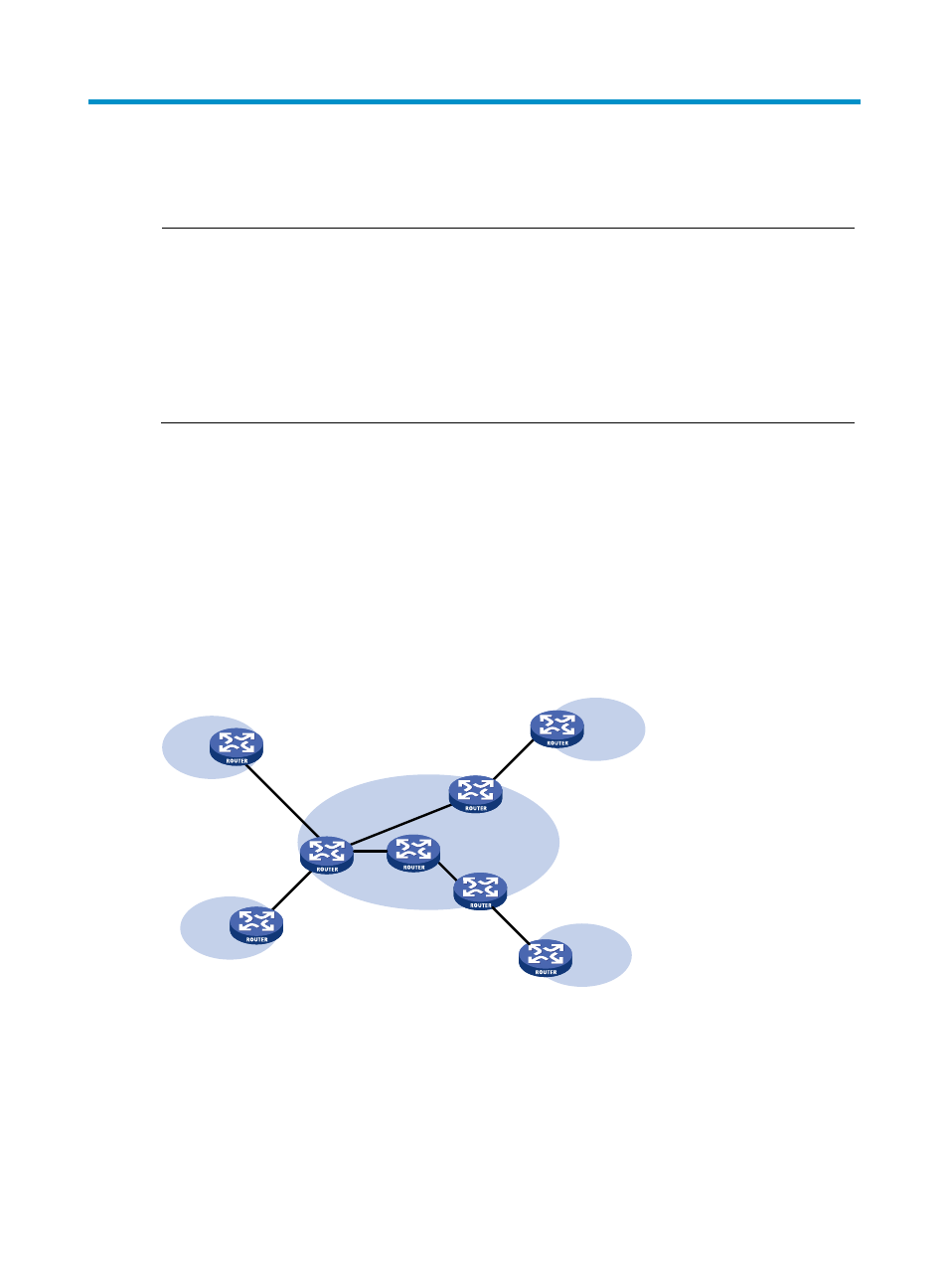
Figure 46 Network diagram for MPLS L2VPN
VPN 1
CE 1
CE 2
VPN 1
VPN 2
VPN 2
CE 3
CE 4
PE 1
PE 3
P
PE 2
LSP
ATM VC
ATM VC
ATM VC
ATM VC
Comparison with MPLS L3VPN
Compared with MPLS L3VPN, MPLS L2VPN has the following advantages:
•
High scalability: MPLS L2VPN establishes only Layer 2 connections. It does not involve the routing
information of users. This greatly reduces the load of the PEs and even the load of the whole service
provider network, enabling carriers to support more VPNs and to service more users.