Configuring inter-as option a, Network requirements, Configuration procedure – H3C Technologies H3C S10500 Series Switches User Manual
Page 301
290
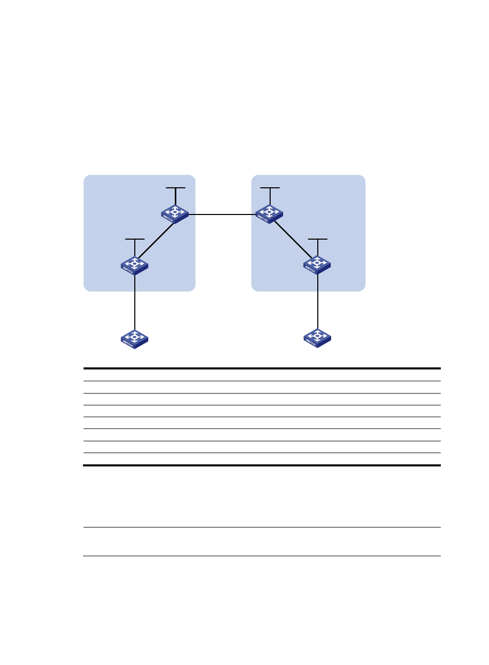
Configuring inter-AS option A
Network requirements
•
CE 1 and CE 2 belong to the same VPN. CE 1 accesses the network through PE 1 in AS 100 and
CE 2 accesses the network through PE 2 in AS 200.
•
Inter-AS MPLS L3VPN is implemented using option A, where the VRF-to-VRF method is used to
manage VPN routes.
•
The MPLS backbone in each AS runs OSPF.
Figure 74 Configure inter-AS option A
Loop0
Loop0
Loop0
Loop0
Vlan-int12
CE 1
CE 2
AS 65001
AS 65002
PE 1
PE 2
ASBR-PE 2
ASBR-PE 1
MPLS backbone
MPLS backbone
AS 100
AS 200
Vlan-int12
Vlan-int12
Vlan-int12
Vlan-int11
Vlan-int11
Vlan-int12
Vlan-int12
Vlan-int11
Vlan-int11
Device
Interface
IP address
Device
Interface
IP address
CE 1
Vlan-int12
10.1.1.1/24
CE 2
Vlan-int12
10.2.1.1/24
PE 1
Loop0
1.1.1.9/32
PE 2
Loop0
4.4.4.9/32
Vlan-int12
10.1.1.2/24
Vlan-int12
10.2.1.2/24
Vlan-int11
172.1.1.2/24
Vlan-int11
162.1.1.2/24
ASBR-PE 1
Loop0
2.2.2.9/32
ASBR-PE 2
Loop0
3.3.3.9/32
Vlan-int11
172.1.1.1/24
Vlan-int11
162.1.1.1/24
Vlan-int12
192.1.1.1/24
Vlan-int12
192.1.1.2/24
Configuration procedure
1.
Configure an IGP on the MPLS backbone to ensure IP connectivity in the backbone
This example uses OSPF. (Details not shown)
NOTE:
The 32-bit loopback interface address used as the LSR ID needs to be advertised by OSPF.
After you complete the configurations, each ASBR PE and the PE in the same AS can establish OSPF
adjacencies. Issue the display ospf peer command. The output shows that the adjacencies reach the Full
state, and that PEs can learn the routes to the loopback interfaces of each other.