Configuration procedure – H3C Technologies H3C S10500 Series Switches User Manual
Page 214
203
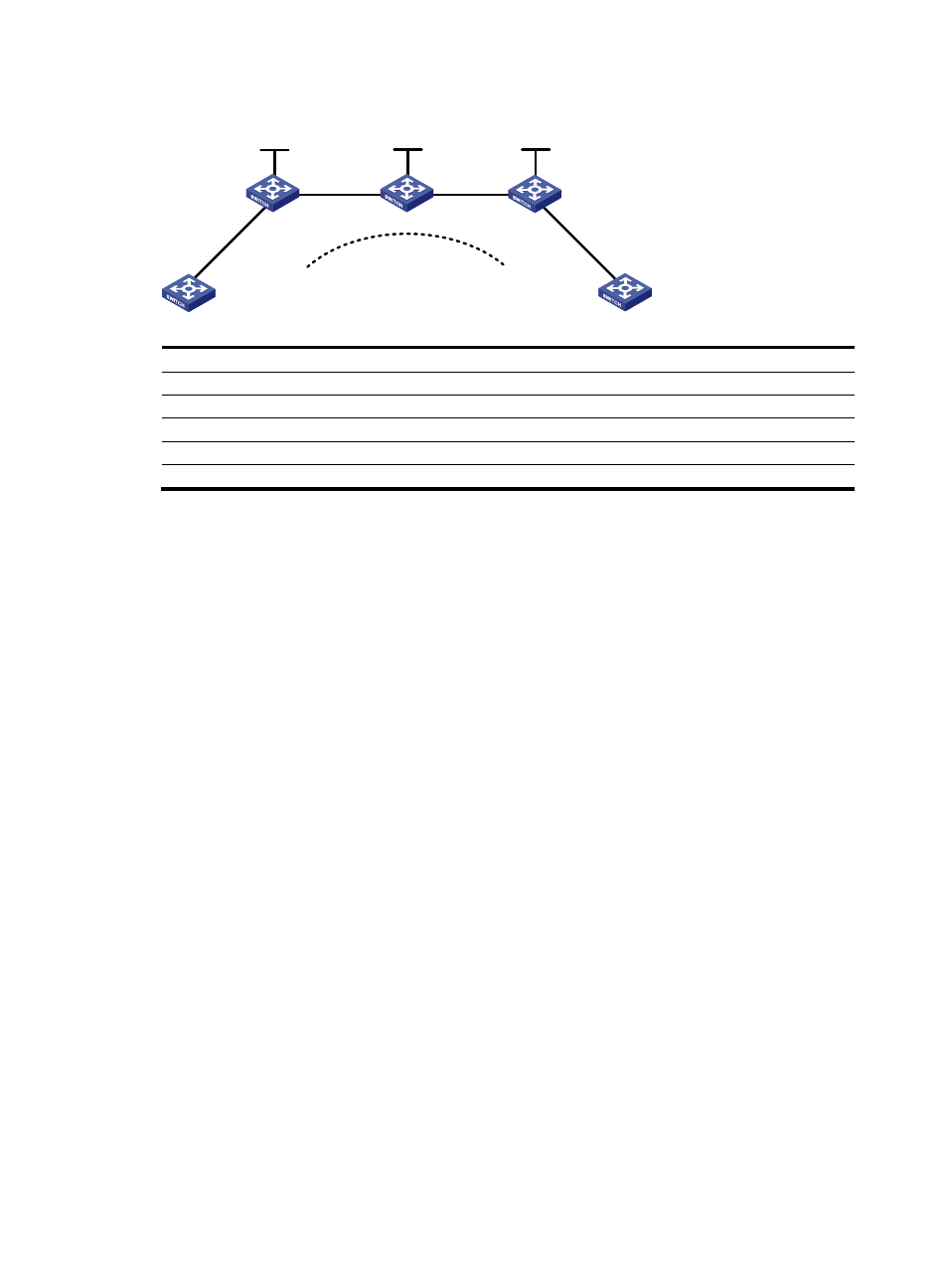
Figure 48 Network diagram for configuring a remote CCC connection
CE 1
CE 2
Remote CCC connection
PE 1
PE 2
P
Vlan-int30
Vlan-int30
Vlan-int20
Vlan-int20
Vlan-int10
Vlan-int10
Vlan-int10
Vlan-int10
Loop0
Loop0
Loop0
Device Interface IP
address
Device Interface IP
address
CE 1
Vlan-int10
100.1.1.1/24
P
Loop0
10.0.0.2/32
PE 1
Loop0
10.0.0.1/32
Vlan-int20
10.2.2.2/24
Vlan-int30 10.1.1.1/24
Vlan-int30 10.1.1.2/24
CE 2
Vlan-int10
100.1.1.2/24
PE 2
Loop0
10.0.0.3/32
Vlan-int20
10.2.2.1/24
Configuration procedure
The following are the main steps to the configuration:
•
Create remote CCC connections on the PEs. No static LSP is required on the PEs.
•
Configure two static LSPs on the P device for packets to be transferred in both directions.
The following is the detailed configuration procedure:
1.
Configure CE 1.
[Sysname] sysname CE1
[CE1] interface vlan-interface 10
[CE1-Vlan-interface10] ip address 100.1.1.1 24
2.
Configure PE 1.
# Configure the LSR ID and enable MPLS globally.
[Sysname] sysname PE1
[PE1] interface loopback 0
[PE1-LoopBack0] ip address 10.0.0.1 32
[PE1-LoopBack0] quit
[PE1] mpls lsr-id 10.0.0.1
[PE1] mpls
[PE1-mpls] quit
# Enable L2VPN and MPLS L2VPN.
[PE1] l2vpn
[PE1-l2vpn] mpls l2vpn
[PE1-l2vpn] quit
# Configure interface VLAN-interface 30 and enable MPLS.
[PE1] interface vlan-interface 30
[PE1-Vlan-interface30] ip address 10.1.1.1 24