Network requirements, Configuration procedure – H3C Technologies H3C S10500 Series Switches User Manual
Page 193
182
[NPE3-GigabitEthernet1/0/1-srv1000] xconnect vsi aaa
[NPE3-GigabitEthernet1/0/1-srv1000] quit
5.
Verify the configuration.
After completing previous configurations, execute the display vpls connection command on the PEs. You
will see that a PW connection in up state has been established.
Configuring BFD in an H-VPLS network to detect errors of the
main link
Network requirements
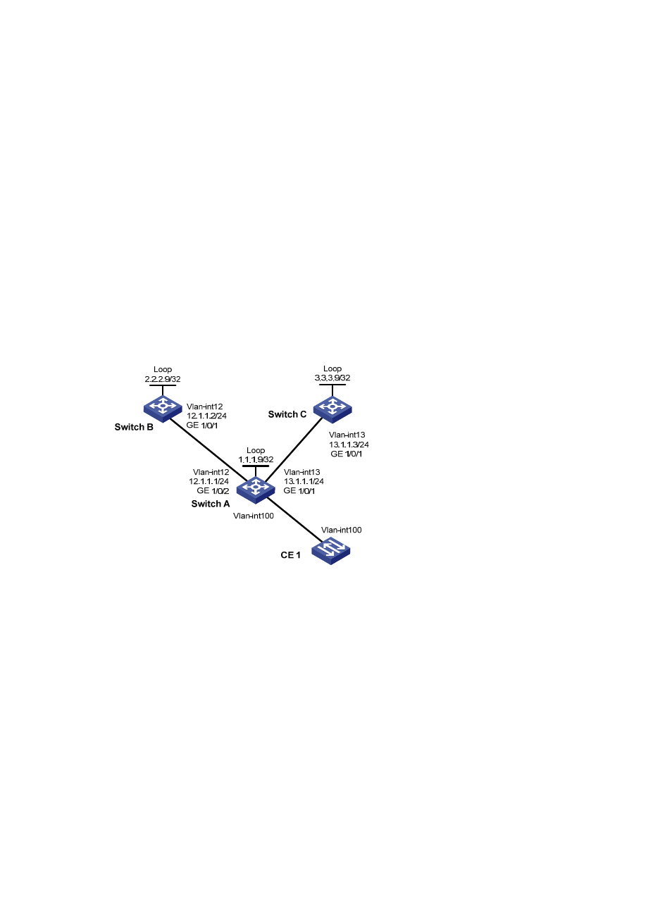
In the H-VPLS network, Switch A is the UPE, Switch B is the main NPE and Switch C is the backup NPE.
Enable MPLS on the interfaces connecting the switches, and enable OSPF on the switches to ensure
reachability at the network layer.
It is required that when the link between Switch A and Switch B is down, the link failure be detected and
informed to the MPLS LDP protocol for fast PW switchover.
Figure 45 Network diagram for configuring BFD in an H-VPLS network for main link detection
Configuration procedure
1.
Configure basic MPLS.
# Configure Switch A.
[SwitchA] mpls lsr-id 1.1.1.9
[SwitchA] mpls
[SwitchA-mpls] quit
[SwitchA] mpls ldp
[SwitchA-mpls-ldp] quit
[SwitchA] mpls ldp remote-peer switchb
[SwitchA-mpls-ldp-remote-switchb] remote-ip 2.2.2.9
[SwitchA-mpls-ldp-remote-switchb] remote-ip bfd
[SwitchA-mpls-ldp-remote-switchb] quit
[SwitchA] mpls ldp remote-peer switchc
[SwitchA-mpls-ldp-remote-switchc] remote-ip 3.3.3.9