Configuration procedure – H3C Technologies H3C S10500 Series Switches User Manual
Page 366
355
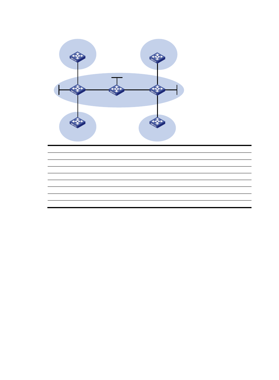
Figure 84 Configure IPv6 MPLS L3VPNs
CE 1
Loop0
Loop0
Loop0
PE 1
PE 2
Vlan-int11
Vlan-int11
Vlan-int12
Vlan-int12
Vlan-int12
Vlan-int13
Vlan-int13
Vlan-int11
Vlan-int11
CE 3
CE 2
CE 4
Vlan-int13
Vlan-int12
Vlan-int13
VPN 1
VPN 1
VPN 2
VPN 2
MPLS backbone
AS 65410
AS 65430
AS 65420
AS 65440
P
Device
Interface
IP address
Device
Interface
IP address
CE 1
Vlan-int11
2001:1::1/64
P
Loop0
2.2.2.9/32
PE 1
Loop0
1.1.1.9/32
Vlan-int12
172.2.1.1/24
Vlan-int11
2001:1::2/64
Vlan-int13
172.1.1.2/24
Vlan-int13
172.1.1.1/24
PE
2
Loop0
3.3.3.9/32
Vlan-int12
2001:2::2/64
Vlan-int12
172.2.1.2/24
CE 2
Vlan-int12
2001:2::1/64
Vlan-int11
2001:3::2/64
CE 3
Vlan-int11
2001:3::1/64
Vlan-int13
2001:4::2/64
CE
4
Vlan-int13
2001:4::1/64
Configuration procedure
1.
Configure OSPF on the MPLS backbone to achieve IP connectivity among the PEs and the P switch.
# Configure PE 1.
[PE1] interface loopback 0
[PE1-LoopBack0] ip address 1.1.1.9 32
[PE1-LoopBack0] quit
[PE1] interface vlan-interface 13
[PE1-Vlan-interface13] ip address 172.1.1.1 24
[PE1- Vlan-interface13] quit
[PE1] ospf
[PE1-ospf-1] area 0
[PE1-ospf-1-area-0.0.0.0] network 172.1.1.0 0.0.0.255
[PE1-ospf-1-area-0.0.0.0] network 1.1.1.9 0.0.0.0
[PE1-ospf-1-area-0.0.0.0] quit
[PE1-ospf-1] quit
# Configure the P switch.
system-view
[P] interface loopback 0