Configuring bgp as number substitution, Network requirements, Configuration procedure – H3C Technologies H3C S10500 Series Switches User Manual
Page 347
336
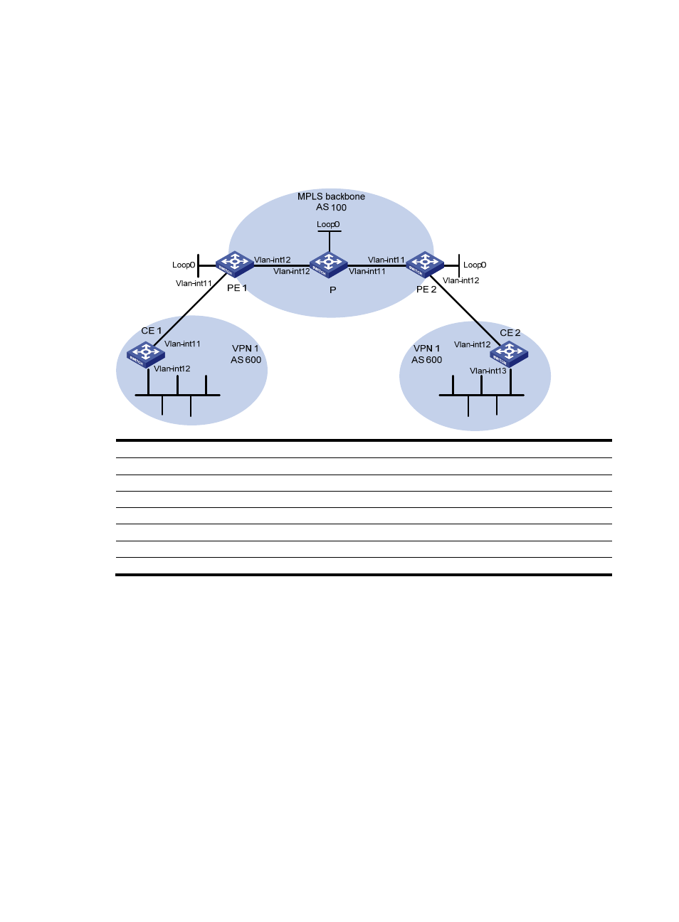
Configuring BGP AS number substitution
Network requirements
As shown in
, CE 1 and CE 2 belong to VPN 1 and are connected to PE 1 and PE 2 respectively.
In addition, they use the same AS number 600.
Figure 81 Configure BGP AS number substitution
Device
Interface
IP address
Device
Interface
IP address
CE 1
Vlan-int11
10.1.1.1/24
P
Loop0
2.2.2.9/32
Vlan-int12
100.1.1.1/24
Vlan-int11
30.1.1.1/24
PE 1
Loop0
1.1.1.9/32
Vlan-int12
20.1.1.2/24
Vlan-int11
10.1.1.2/24
PE
2
Loop0
3.3.3.9/32
Vlan-int12
20.1.1.1/24
Vlan-int11
30.1.1.2/24
CE 2
Vlan-int12
10.2.1.1/24
Vlan-int12
10.2.1.2/24
Vlan-int13
200.1.1.1/24
Configuration procedure
1.
Configuring basic MPLS L3VPN
•
Configure OSPF on the MPLS backbone to allow the PEs and P device to learn the routes of the
loopback interfaces from each other.
•
Configure MPLS basic capability and MPLS LDP on the MPLS backbone to establish LDP LSPs.
•
Establish MP-iBGP peer relationship between the PEs to advertise VPN IPv4 routes.
•
Configure the VPN instance of VPN 1 on PE 2 to allow CE 2 to access the network.
•
Configure the VPN instance of VPN 1 on PE 1 to allow CE 1 to access the network.
•
Configure BGP between PE 1 and CE 1, and between PE 2 and CE 2 to inject routes of CEs into PEs.
After completing the configurations, issue the display ip routing-table command on CE 2. You can see
that CE 2 has learned the route to network segment 10.1.1.0/24, where the interface used by CE 1 to
access PE 1 resides; but has not learned the route to the VPN (100.1.1.0/24) behind CE 1. The situation
on CE 1 is similar.