Frr configuration example, Network requirements – H3C Technologies H3C S10500 Series Switches User Manual
Page 153
142
LSP-Id Destination In/Out-If Name
1.1.1.9:2054 3.3.3.9 -/Vlan4 Tunnel1
NOTE:
Configuring ordinary CR-LSP backup is almost the same as configuring hot CR-LSP backup except that you
need to replace the mpls te backup hot-standby command with the mpls te backup ordinary command.
Unlike in hot CR-LSP backup where a secondary tunnel is created immediately upon creation of a primary
tunnel, in ordinary CR-LSP backup, a secondary CR-LSP is created only after the primary LSP goes down.
6.
Create a static route for routing MPLS TE tunnel traffic
[SwitchA] ip route-static 20.1.1.2 24 tunnel 1 preference 1
Perform the display ip routing-table command on Switch A. You can see a static route entry with Tunnel1
as the outgoing interface.
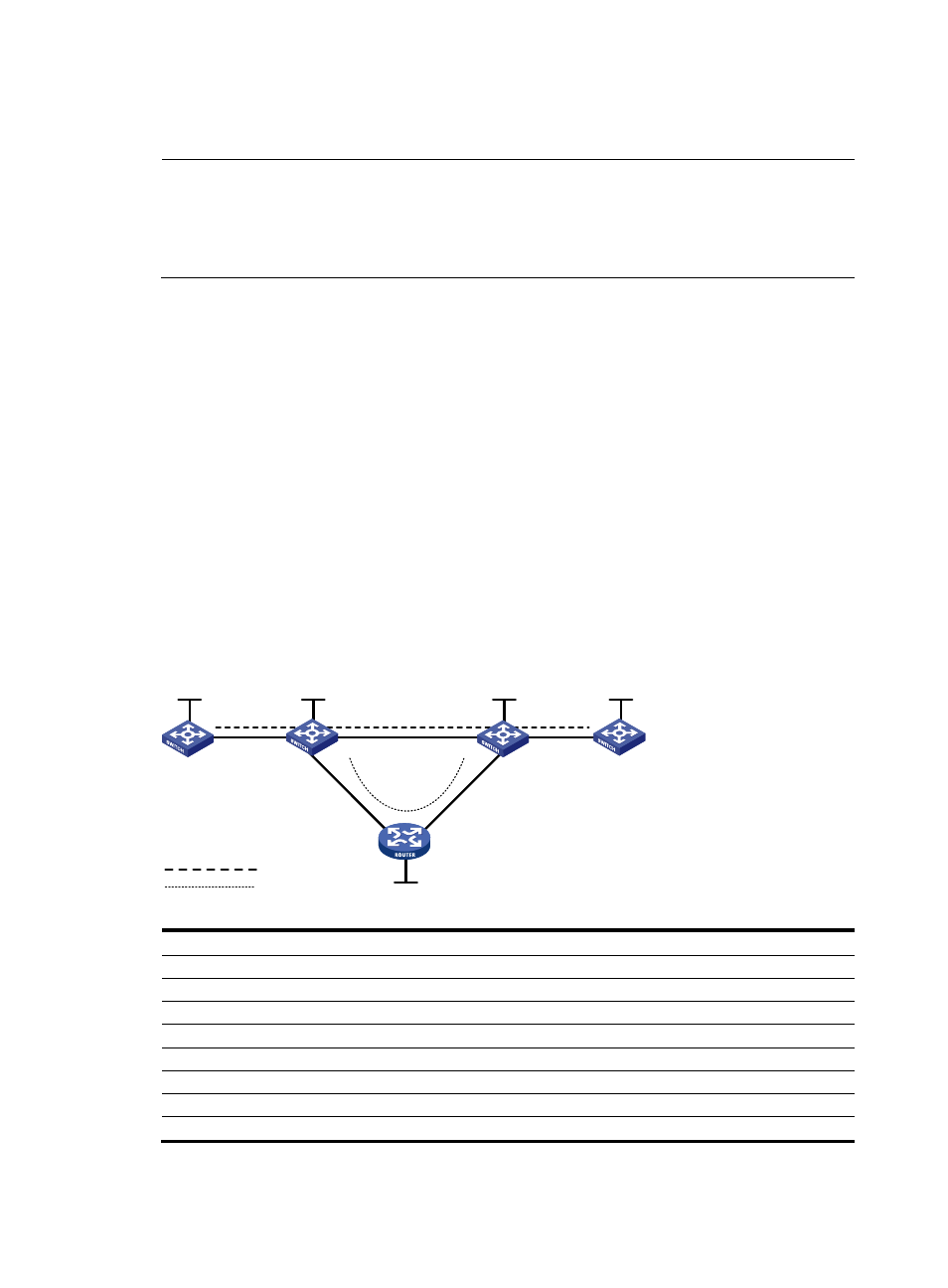
FRR configuration example
Network requirements
On a primary LSP Switch A Switch B Switch C
→
→
Switch D, use FRR to protect the link Switch B
→
→
Switch C.
•
Create a bypass LSP that traverses the path Switch B Switch E Switch C. Switch B is the PLR and
→
→
Switch C is the MP.
•
Explicitly route the primary TE tunnel and the bypass TE tunnel with the signaling protocol being
RSVP-TE.
Figure 36 Link protection using the FRR approach
Switch A
Switch B
Switch C
Switch D
Switch E
Vlan-int1
Loop0
Loop0
Loop0
Loop0
Vlan-int1
Vlan-int2
Vlan-int2
Vlan-int3
Vlan-int3
Vlan-int4
Vlan-int4
Primary LSP
Bypass LSP
Vlan-int5
Vlan-int5
Loop0
Device
Interface
IP address
Device
Interface
IP address
Switch A
Loop0
1.1.1.1/32
Switch E
Loop0
5.5.5.5/32
Vlan-int1
2.1.1.1/24
Vlan-int4
3.2.1.2/24
Switch B
Loop0
2.2.2.2/32
Vlan-int5
3.3.1.1/24
Vlan-int1
2.1.1.2/24
Switch
C
Loop0
3.3.3.3/32
Vlan-int2
3.1.1.1/24
Vlan-int3
4.1.1.1/24
Vlan-int4
3.2.1.1/24
Vlan-int2
3.1.1.2/24
Switch D
Loop0
4.4.4.4/32
Vlan-int5
3.3.1.2/24
Vlan-int3
4.1.1.2/24